Control method based on power supply system and related device

A control method and power supply system technology, which is applied in the direction of circuit devices, selective AC load connection devices, electrical components, etc., can solve problems such as bypass full load, reduce the operating efficiency of the power supply system, and affect the load capacity of the power supply system, so as to improve The effect of operating efficiency

Active Publication Date: 2020-12-04
KEHUA DATA CO LTD +1
View PDF6 Cites 2 Cited by
  • Summary
  • Abstract
  • Description
  • Claims
  • Application Information

AI Technical Summary

Problems solved by technology

[0003] In the prior art, people usually set up multiple power supply modules (such as: Uninterruptible Power Supply (UPS, Uninterruptible Power Supply)) in a power supply system, and supply power through the bypass of each power supply module to obtain a high-power power supply system, but In the actual process, due to differences in hardware, the currents of bypass circuits on different power supply modules cannot be guaranteed to be the same. Seriously affect the load capacity of the entire power supply system and reduce the operating efficiency of the power supply system

Method used


Image

  • Control method based on power supply system and related device
  • Control method based on power supply system and related device
  • Control method based on power supply system and related device

Examples


Embodiment 1

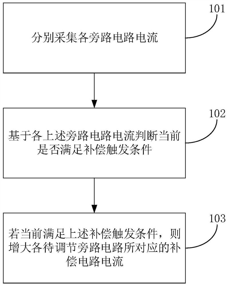
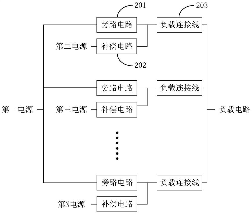
[0042] The present application provides a control method based on a power supply system. The above power supply system includes more than two bypass circuits and more than one compensation circuit. The output ends of each of the above bypass circuits are respectively electrically connected to a load connection line. Used for electrical connection with the load circuit, the above-mentioned compensation circuit is used for inputting current to the load connection line corresponding to the corresponding bypass circuit, wherein the above-mentioned bypass circuit has a first resistance, the above-mentioned load connection line has a second resistance, and the above-mentioned first The first resistance includes line resistance and / or external resistance, and the second resistance includes line resistance and / or external resistance;

[0043] In the embodiment of the present application, both the bypass circuit and the load connecting wire have a certain resistance value, and the resis...

Embodiment 2

[0078] The present application also provides a control device based on a power supply system. The above power supply system includes more than two bypass circuits and more than one compensation circuit. The output ends of each of the above bypass circuits are respectively electrically connected to a load connection line. The line is used to electrically connect with the load circuit, and the above-mentioned compensation circuit is used to input current to the load connection line corresponding to the corresponding bypass circuit, wherein the above-mentioned bypass circuit has a first resistance, and the above-mentioned load connection line has a second resistance. The first resistance includes line resistance and / or external resistance, and the second resistance includes line resistance and / or external resistance;

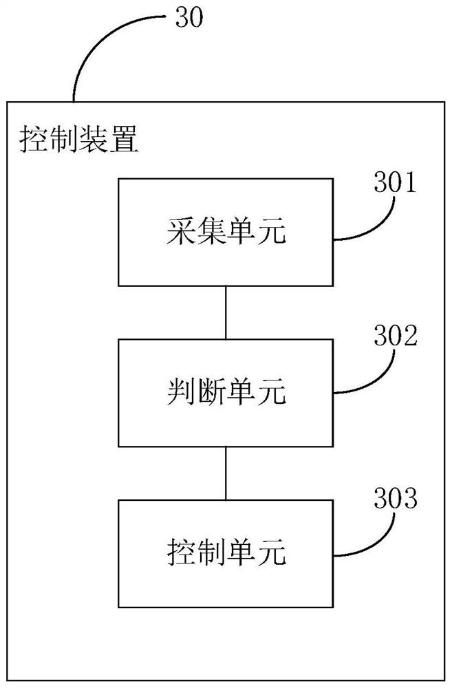
[0079] Such as image 3 As shown, the above-mentioned control device 30 includes:

[0080] A collection unit 301, configured to separately collect the current of ...

Embodiment 3

[0098] The present application also provides a control device based on a power supply system, such as Figure 4 As shown, the control device based on the power supply system in the embodiment of the present application includes: a memory 401, a processor 402, and a computer program stored in the memory 401 and operable on the processor 402, wherein: the memory 401 is used to store the software program As well as modules, the processor 402 executes various functional applications and data processing by running software programs and modules stored in the memory 401. The above-mentioned power supply system includes more than two bypass circuits and more than one compensation circuit. Each of the above-mentioned bypass circuits The output terminals are respectively electrically connected to a load connecting line, the above-mentioned load connecting line is used for electrically connecting with the load circuit, and the above-mentioned compensation circuit is used for inputting cur...


PUM


Abstract

The invention provides a control method based on a power supply system and a related device, and relates to the technical field of circuit control. The control method comprises the following steps: respectively acquiring current of each bypass circuit; judging whether the current meets a compensation triggering condition or not based on the current of each bypass circuit; and if the compensation triggering condition is met currently, increasing the compensation circuit current corresponding to each bypass circuit to be adjusted to increase the current input to the corresponding load connectingline by the compensation circuit corresponding to each bypass circuit to be adjusted, thereby reducing the current input to the corresponding load connecting line by each bypass circuit to be adjusted, and improving the adjustment precision. Current sharing of the bypass circuits in the power supply system is achieved, the situation that one part of the bypass circuits are fully loaded and the other part of the bypass circuits are not fully loaded is avoided, and the operation efficiency of the power supply system is improved.

Description

technical field [0001] The present application relates to the technical field of circuit control, in particular to a control method and related devices based on a power supply system. Background technique [0002] With the development of the times, people have higher and higher demands on the power supply system, how to improve the operating efficiency of the power supply system has become an urgent problem to be solved in this field. [0003] In the prior art, people usually set up multiple power supply modules (such as: Uninterruptible Power Supply (UPS, Uninterruptible Power Supply)) in a power supply system, and supply power through the bypass of each power supply module to obtain a high-power power supply system, but In the actual process, due to differences in hardware, the currents of bypass circuits on different power supply modules cannot be guaranteed to be the same. Seriously affect the load capacity of the entire power supply system and reduce the operating effi...

Claims


Application Information

Patent Timeline
Patent Type & Authority Applications(China)
IPC IPC(8): H02J3/00
CPCH02J3/007
Inventor 陈文佳吴庆彬周超伟李丞杰钟小帆
Owner KEHUA DATA CO LTD
Why Eureka
Try Eureka