Lifting column control system
A control system and a lifting column technology, applied in the field of lifting column control, can solve the problems of lifting column lifting obstacles, difficult to accurately identify vehicles, few lifting columns and inability to realize multiple remote control operations, etc., to avoid obstacles and achieve accurate automatic operation. Effect
- Summary
- Abstract
- Description
- Claims
- Application Information
AI Technical Summary
Problems solved by technology
Method used
Image

Examples
Embodiment 1
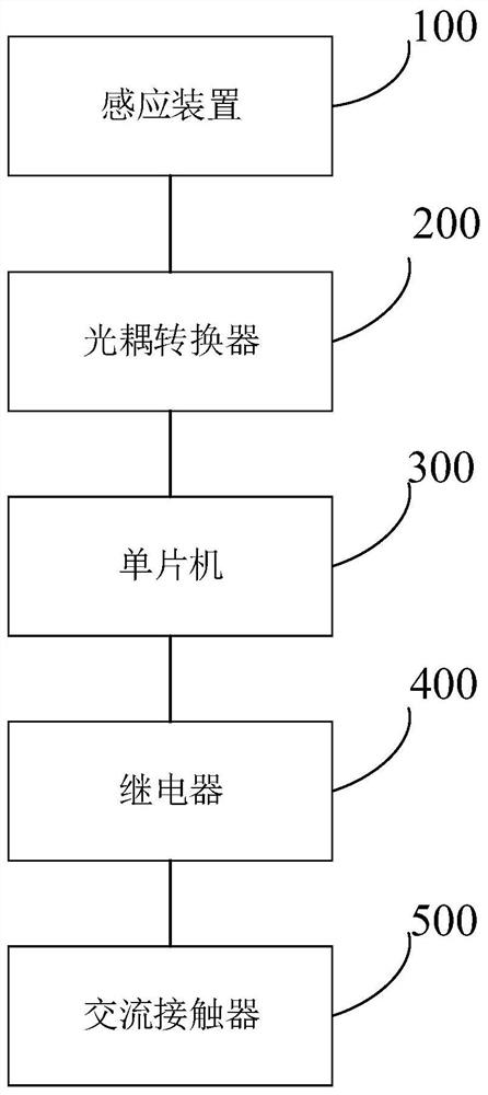
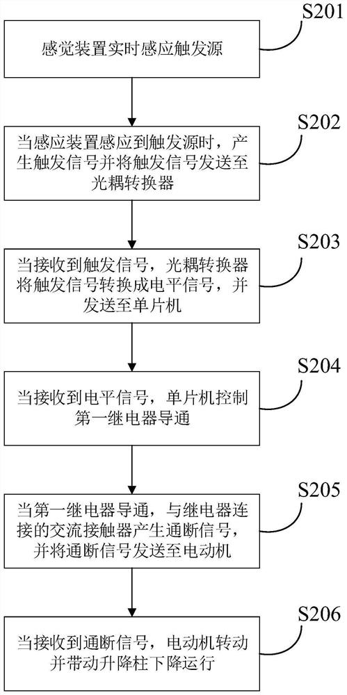
[0036] Such as figure 1 with Figure 5 As shown, a lifting column control system according to an embodiment of the present invention includes: an induction device 100, a controller and an AC contactor 500; the controller includes an optocoupler converter 200, a single-chip microcomputer 300, and a relay 400; Sensing the trigger source, sending a trigger signal to the optocoupler converter 200 after sensing the trigger source; the optocoupler converter 200 is used to convert the trigger signal into a level signal, and send the level signal to the single-chip microcomputer 300; To identify the level signal, and control the conduction of the relay 400 according to the recognized level signal; the AC contactor 500 is used to generate an on-off signal and output it externally after the relay 400 is turned on.
[0037] In this embodiment, the control system of the lifting column 8 further includes a motor, which is used to receive the on-off signal output by the AC contactor 500 , ...
Embodiment 2
[0059] see figure 2 , Figure 5 with Image 6 , According to another embodiment of the present invention, a lifting column control system is provided, including: an induction device 100 and a controller; the controller includes an optocoupler converter 200, a single-chip microcomputer 300, and a relay 400; wherein: the induction device 100 is used for Sensing the trigger source, sending a trigger signal to the optocoupler converter 200 after sensing the trigger source; the optocoupler converter 200 is used to convert the trigger signal into a level signal, and sends the level signal to the single-chip microcomputer 300; the single-chip microcomputer 300 is used for The level signal is identified, and the relay 400 is controlled to conduct according to the identified level signal.
[0060] In this embodiment, the lifting column control system further includes a motor, which is used to rotate and drive the external lifting column 8 to lift after the relay 400 is turned on.
...
Embodiment 3
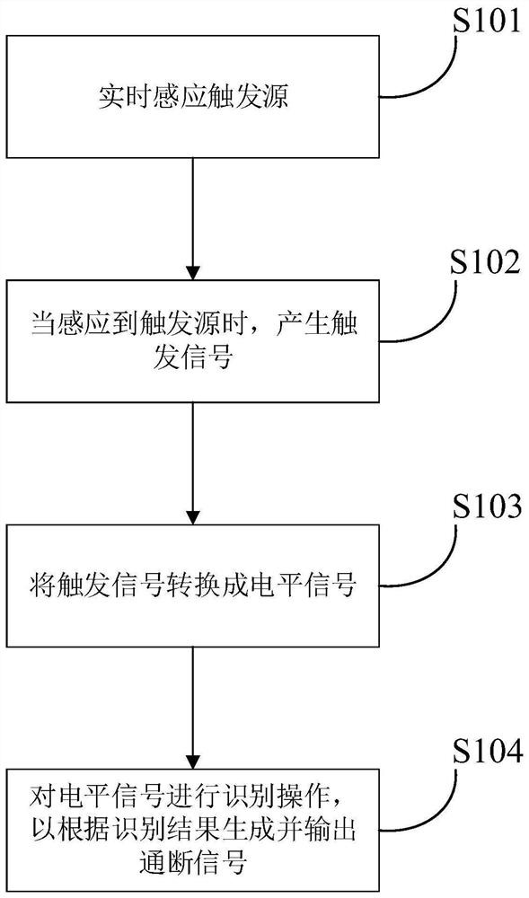
[0082] According to another embodiment of the present invention, a lifting column control method is provided, see figure 1 , figure 2 with Figure 5 ,include:
[0083] S101: Real-time sensing trigger source.
[0084] In this embodiment, the sensing device 100 detects the trigger source in real time; the sensing device 100 includes a camera module 10, a ground sensing coil and an infrared sensor 9; the ground sensing coil includes a first ground sensing coil 6 and a second ground sensing coil 7; the sensing device 100 is in the state of detecting the trigger source in real time; one of the camera module 10 , ground sensing coil and infrared sensor 9 senses the trigger source to generate a trigger signal.
[0085] For example, when the camera module 10 captures a vehicle or a license plate, and the infrared sensor 9 or the ground induction coil senses the vehicle, a trigger signal is sent to the optocoupler converter 200; Column 8 carries out lifting motion.
[0086] In th...
PUM
 Abstract
Description
Claims
Application Information
 - Generate Ideas
- Intellectual Property
- Life Sciences
- Materials
- Tech Scout
- Unparalleled Data Quality
- Higher Quality Content
- 60% Fewer Hallucinations
Browse by: Latest US Patents, China's latest patents, Technical Efficacy Thesaurus, Application Domain, Technology Topic, Popular Technical Reports.
© 2025 PatSnap. All rights reserved.Legal|Privacy policy|Modern Slavery Act Transparency Statement|Sitemap|About US| Contact US: help@patsnap.com