
Carbon fiber and metal connecting structure and connecting method thereof

A connection structure, carbon fiber technology, applied in the direction of ohmic resistance heating parts, heating element shapes, etc., can solve problems such as unfavorable production and rapid installation, large longitudinal stress at the contact point, large damage to carbon fiber filaments, etc., to improve heating life and Effect of heat supply quality, indirect contact area increase, and contact resistivity reduction

Pending Publication Date: 2020-12-08
TIANJIN UNIV
View PDF5 Cites 1 Cited by
  • Summary
  • Abstract
  • Description
  • Claims
  • Application Information

AI Technical Summary

Problems solved by technology

This method connects tightly and firmly, but the contact area is relatively small, and the operation is difficult; patent CN104241910A discloses a joint device that uses a compression buckle and a locking buckle to connect carbon fiber cables. This method improves the connection stability, but the structure is complicated. Facilitate production and quick installation; Patent CN104158011A adds carbon powder to plastic raw materials that can be injection molded, and mixes it into carbon-plastic synthetic powder, and injects the carbon-plastic synthetic powder on the carbon fiber heating wire terminal and the metal wire terminal. , to form a plastic conductive joint that fixedly connects the carbon fiber heating wire and the metal wire. This method is safe and reliable, and the contact area is large, but the production process is cumbersome and difficult to realize; the patent CN205693910U is fixedly connected by welding at the junction of the metal wire and the carbon fiber wire, and the carbon fiber wire It is composed of multiple carbon fiber wires arranged in parallel, and the insulating tube is filled with magnesium oxide powder, and the heating cable is equipped with carbon fiber wires.
This utility model has a high safety factor, but it will cause great damage to carbon fiber filaments and a high failure rate of carbon fibers; patents CN205830058U, CN203721908U, CN203301757U, CN202564574U, CN205436444U, etc. use metal guides such as compression pieces, ferrules or tie bands, and mechanical pressure The carbon fiber and metal wires are connected in a tight way, which is firm and reliable, but the contact area is small, the heat is serious, and the life of the joint is short
Moreover, the longitudinal stress at the contact point is large, which has caused the fiber to break and lead to the failure of the connection
[0004] As far as the current achievements are concerned, many patents focus on whether the connecting joint is firm and reliable, but they do not involve reducing the sharp and tough end, increasing the contact area, reducing the resistance change rate at the contact point, reducing heat at the joint, improving the life of the connecting joint, and the actual operation is simple. related patents

Method used


Image

  • Carbon fiber and metal connecting structure and connecting method thereof
  • Carbon fiber and metal connecting structure and connecting method thereof
  • Carbon fiber and metal connecting structure and connecting method thereof

Examples


Embodiment Construction

[0019] The present invention will be described in further detail below in conjunction with the accompanying drawings and specific embodiments. It should be understood that the specific embodiments described here are only used to explain the present invention, not to limit the present invention.

[0020] The resistance stability of the heating element is an important index to evaluate the quality of the element, and the resistance change rate under a certain temperature rise is used To represent,

[0021]

[0022] where R 0 is the cold resistance of the carbon fiber heating element, and R is the dynamic resistance of the carbon fiber heating element. Let the monofilament length of carbon fiber be L, the diameter of monofilament be d, and the total number of monofilaments be n cf , the cold resistivity of carbon fiber material ρ cf , n c The number of fiber overlapping points between carbon fiber monofilaments is equivalent to increasing the parallel connection between ...


PUM


Abstract

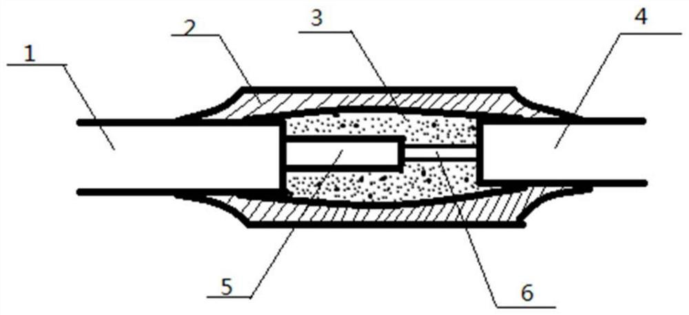
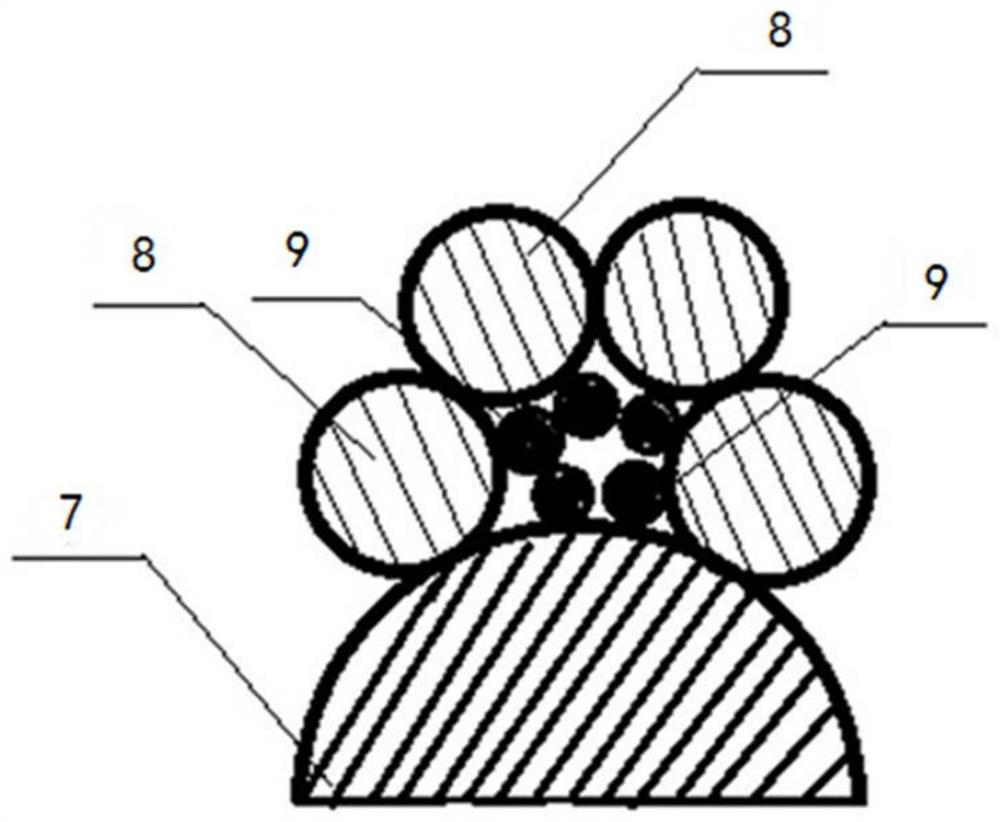
The invention discloses a carbon fiber and metal connecting structure and a connecting method thereof. The connecting structure comprises a carbon fiber wire and a metal wire which are connected witheach other, the joint of the carbon fiber wire and the metal wire is coated with a phenolic resin binder, and conductive particles are doped in the phenolic resin binder; and the joint of the carbon fiber wire and the metal wire is sleeved with an insulating heat-shrinkable sleeve. The connecting method comprises the following steps: (1) removing a silica gel outer sleeve at the joint of the carbon fiber wire to expose a carbon fiber wire bundle, and removing the outer sleeve at the joint of the metal wire to expose the metal wire; (2) inserting a metal wire into the carbon fiber bundle to enable the carbon fiber bundle to surround the periphery of the metal wire; and (3) coating the joint of the carbon fiber bundle and the metal wire with the phenolic resin binder doped with the conductive particles, completely soaking the carbon fiber bundle and the metal wire, and sleeving the joint with the insulating heat-shrinkable sleeve after the phenolic resin binder is naturally air-dried.

Description

technical field [0001] The invention designs a connection structure between carbon fibers and metal wires, which uses a binder doped with conductive particle materials to connect the carbon fibers and metal wires. This method is suitable for the connection of carbon fiber heating wire and metal copper wire. Background technique [0002] Carbon fiber is a fibrous carbon material, as an electric heater, it has many valuable electrical, thermal and mechanical properties. In recent years, the core heating elements of many energy-saving heating equipment have been gradually upgraded from the previously commonly used metal materials to carbon fiber materials. In the actual project of carbon fiber heating wire electric floor heating, the contact performance of the connection between carbon fiber and metal wire affects the life and heating effect of carbon fiber heating wire to a certain extent. In the prior art, a metal clip is used to connect the carbon fiber heating wire and th...

Claims


Application Information

Patent Timeline
Patent Type & Authority Applications(China)
IPC IPC(8): H05B3/56H05B3/02
CPCH05B3/02H05B3/56
Inventor 杨俊红贾晨史鑫钰马睿杰
Owner TIANJIN UNIV
Learn More