
Ankle joint artificial prosthesis

An artificial prosthesis, ankle joint technology, applied in ankle joints, joint implants, joint implants, etc., can solve the problems of reducing interface, reducing prosthesis-bone interface shear force, torsional stress, pain, etc. , to reduce the effect of tibial osteotomy

Pending Publication Date: 2020-12-11
THE PEOPLES HOSPITAL SHAANXI PROV
View PDF7 Cites 0 Cited by
  • Summary
  • Abstract
  • Description
  • Claims
  • Application Information

AI Technical Summary

Problems solved by technology

The first generation is a bone cement-type restrictive prosthesis; each component and the bone are filled with bone cement, and the tibial and talar components are connected by a hinge, which has the characteristics of strong stability; but the disadvantages are also obvious, such as implantation A large number of osteotomies are required during the process, and osteolysis around the prosthesis is high, causing loosening and subsidence of the prosthesis, and a high rate of surgical failure
The second generation is a biological non-restrictive prosthesis; a polyethylene liner is added between the prosthetic tibial and talar components, which reduces the restriction and reduces the amount of osteotomy during the operation; the biological fixation method reduces the gap between materials At the same time, the shear force and torsional stress of the prosthesis-bone interface are reduced, and the loosening rate of the prosthesis is reduced; however, due to the wear of the polyethylene liner, the stability of the artificial joint will gradually decrease, and pain, impact or even artificial joint dislocation
The contact surface between the talar component and the talus of the INBONE total ankle prosthesis is designed with a "talar stem" and two "anterior pegs" in order to increase the stability of the talar component, but limited by the surgical approach, the "talar stem" and " "Anterior peg" is not perpendicular to the underside of the talar component, i.e. optimal stabilization of the talar component is not achieved, leading to an increased risk of prosthetic loosening

Method used


Image

  • Ankle joint artificial prosthesis
  • Ankle joint artificial prosthesis
  • Ankle joint artificial prosthesis

Examples


Embodiment Construction

[0058] Embodiments of the present invention are described in detail below, examples of which are shown in the drawings, wherein the same or similar reference numerals designate the same or similar elements or elements having the same or similar functions throughout. The embodiments described below by referring to the figures are exemplary and are intended to explain the present invention and should not be construed as limiting the present invention.

[0059] In describing the present invention, it should be understood that the terms "center", "longitudinal", "transverse", "length", "width", "thickness", "upper", "lower", "front", " Orientation indicated by rear, left, right, vertical, horizontal, top, bottom, inside, outside, clockwise, counterclockwise, etc. The positional relationship is based on the orientation or positional relationship shown in the drawings, which is only for the convenience of describing the present invention and simplifying the description, rather than ...


PUM


Abstract

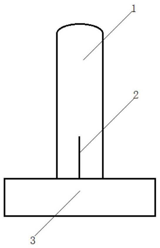
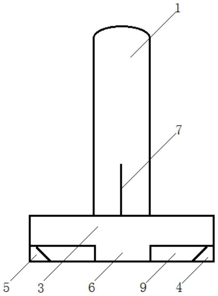
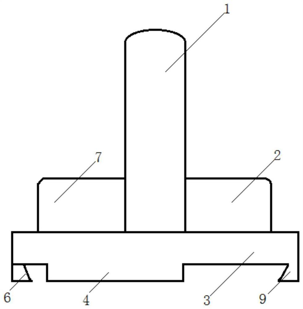
The invention provides an ankle joint artificial prosthesis. The ankle joint artificial prosthesis comprises a shin assembly, an astragalus assembly and a liner, wherein the shin assembly adopts design of a long shin intramedullary positioning rod, and can be matched with a mechanical axis of a lower limb to the maximum extent during surgical implantation; the design of front and rear anti-rotor wings is adopted to limit rotational displacement of an implanted assembly; the design of a fixed platform of a limiting sliding groove structure is adopted, and lateral shin osteotomy in an operationis reduced to the maximum extent; and an astragalus assembly body adopts design of an arc-shaped top with a groove, a polyethylene liner can only slide along the groove of the arc-shaped top, and thesemi-limiting characteristic of a full-ankle joint replacement device is achieved. The flat bottom of the assembly body is connected with three cylindrical stabilizing columns with the axes perpendicular to the flat bottom, and therefore, the astragalus assembly can be prevented from sliding and twisting on an astragalus osteotomy face.

Description

technical field [0001] The invention relates to the technical field of medical devices, in particular to an ankle joint artificial prosthesis used for implantation in total ankle joint replacement surgery. Background technique [0002] Ankle degenerative joint disease, ankle inflammatory joint disease, and ankle post-traumatic arthritis can cause pain, swelling, deformity, and even loss of joint function in the ankle joint. Imaging often shows narrow ankle joint space and subchondral bone sclerosis , Osteophyte formation and even articular surface collapse and talus necrosis. The above three diseases all seriously affect the weight-bearing activities of the ankle joint, which can be called disabling diseases. The treatment of the above three diseases can be said to be both beneficial and challenging for both patients and medical workers. At present, the academic circle generally regards ankle degenerative joint disease, inflammatory joint disease and post-traumatic arthriti...

Claims


Application Information

Patent Timeline
Patent Type & Authority Applications(China)
IPC IPC(8): A61F2/42
CPCA61F2/4202A61F2002/4205A61F2002/4207
Inventor 凌鸣易智史纪元
Owner THE PEOPLES HOSPITAL SHAANXI PROV
Learn More