Manufacturing method of chip inductor, and chip inductor manufactured by manufacturing method

A manufacturing method and technology of chip inductors, applied in the direction of inductor/transformer/magnet manufacturing, transformer/inductor components, preventing/reducing unwanted electrical/magnetic effects, etc., can solve the problem of high frequency and ultra-miniaturization Insufficient inductance, inability to meet the requirements of small volume and high inductance, low magnetic permeability of chip inductance, etc., to achieve the effect of improving compression molding effect, low loss, good dispersion and adhesion

Inactive Publication Date: 2020-12-11
POCO HLDG CO LTD +2
View PDF12 Cites 4 Cited by
  • Summary
  • Abstract
  • Description
  • Claims
  • Application Information

AI Technical Summary

Problems solved by technology

In this method, before the coil is pressed, the coil layers of the coil are arranged at intervals and are in a pre-stretched state, so that during the pressing process, the gap between each layer of coil layers is filled with magnetic materials, and the interlayer of the coil after pressing is Separated by magnetic materials, the problem of short circuit between the coil layers is avoided. Since the coil layers are isolated from each other, the pressing pressure will not cause short circuit effects on the coils, so that the pressing pressure can be increased to increase the product density and increase the density. It can make the inductor have better electromagnetic characteristics, but this method also has the above-mentioned high inductance requirements that cannot meet the small volume
[0006] The second method is to use high pressure to press the magnetic powder into shape, then cut a groove in the middle of the magnetic core, sinter at a high temperature, wind the coil at the groove, and finally seal the groove and the coil with magnetic glue. Although it is easy to obtain a magnetic core with a higher magnetic permeability, the magnetic flux leakage phenomenon is prone to occur at the sealant, and the magnetic core withstands pressure difference, which also has the disadvantage of poor comprehensive characteristics.
Although the chip inductors prepared in this way have the advantages of small size and high efficiency, the low material density leads to low magnetic permeability and high loss.
[0008] Disclosed as CN111354562A is a manufacturing method of chip inductors and chip inductors, the manufacturing method is by pressing the alloy soft magnetic powder into a square magnetic core; cutting the square magnetic core into alloy soft magnetic sheets; hole; print conductive silver paste on the alloy soft magnetic sheet to form a silver paste circuit, and the conductive silver paste covers and fills the through hole; stack and glue the next piece of alloy soft magnetic sheet on the silver paste circuit; repeatedly print the silver paste circuit and stack it The step of bonding alloy soft magnetic sheets, the silver paste circuits on two adjacent alloy soft magnetic sheets are connected through through holes and made into chip inductors, which also have the problem of low magnetic permeability
[0009] To sum up, the inductors prepared by the above methods have their own unique advantages. The first one-piece molded inductor and the second cutting method are more difficult to prepare ultra-small inductors, while the third one has ultra-small mass production. , but the magnetic permeability is low, and the product inductance value is low
[0010] Therefore, it is urgent to invent a manufacturing method of high-inductance film-type chip inductors to solve the problem of insufficient high-frequency and ultra-miniature inductors in the future.

Method used


Image

  • Manufacturing method of chip inductor, and chip inductor manufactured by manufacturing method
  • Manufacturing method of chip inductor, and chip inductor manufactured by manufacturing method

Examples


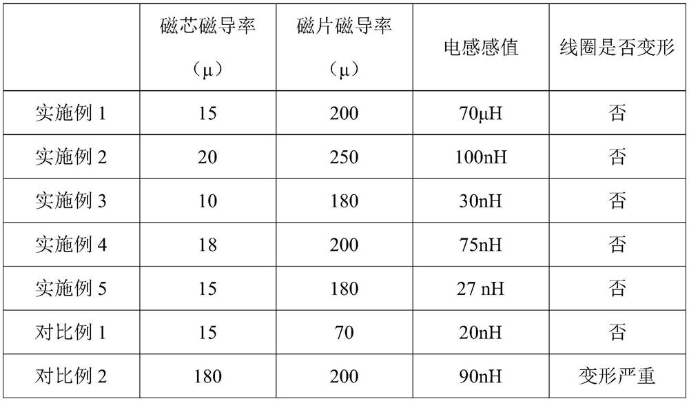
Embodiment 1

[0118] This embodiment provides a method for manufacturing a chip inductor, and the method includes the following steps:

[0119] (1) mixing the first phosphoric acid and alcohol to prepare the first passivation solution; adding the first passivation solution to the iron-silicon spherical powder (iron: 93.5wt%; silicon: 6.5wt%) whose particle diameter D50 is 15 μm, Stir and mix evenly, after the alcohol volatilizes, bake and heat at 150°C for 1.5h to obtain an insulating and coated spherical powder; the amount of the first phosphoric acid is 0.08% of the mass of the spherical powder, and the amount of alcohol is 4% of the mass of the spherical powder ;

[0120] Add the insulating coated spherical powder into bismaleimide polyimide thermosetting epoxy resin and acetone, mix and stir for 8 hours to obtain the first slurry with a viscosity of 150mPa·s; the amount of epoxy resin is 5% of the mass of the spherical powder after the treatment; the consumption of acetone is 12% of th...

Embodiment 2

[0133] This embodiment provides a method for manufacturing a chip inductor, and the method includes the following steps:

[0134](1) Mix the first phosphoric acid and acetone to prepare the first passivation solution; the first passivation solution is added to the spherical powder of sendust with a particle diameter D50 of 5 μm (iron: 85wt%; silicon: 9.6wt%; aluminum 5.4 wt%), stir and mix evenly, after the acetone volatilizes, bake and heat at 100°C for 0.5h to obtain a spherical powder after insulation coating; the amount of the first phosphoric acid is 0.05% of the mass of the spherical powder, and the amount of acetone is spherical powder 1% of powder mass;

[0135] Add the insulating coated spherical powder into bismaleimide polyimide thermosetting epoxy resin and acetone and mix for 12 hours to obtain the first slurry with a viscosity of 200mPa·s; the amount of epoxy resin is 8% of the processed spherical powder mass; the consumption of acetone is 15% of the insulating ...

Embodiment 3

[0147] This embodiment provides a method for manufacturing a chip inductor, and the method includes the following steps:

[0148] (1) Mix the first phosphoric acid and alcohol to prepare the first passivation solution; add the first passivation solution to the iron-nickel spherical powder (iron: 50wt%; nickel: 50wt%) with a particle diameter D50 of 30 μm, stir and mix Evenly, after the alcohol volatilizes, bake and heat at 230°C for 2 hours to obtain an insulating and coated spherical powder; the amount of the first phosphoric acid is 1% of the mass of the spherical powder, and the amount of alcohol is 6% of the mass of the spherical powder;

[0149] Add the insulating-coated spherical powder into bismaleimide polyimide thermosetting epoxy resin and acetone, mix and stir for 3 hours to obtain the first slurry with a viscosity of 10 mPa s; the amount of epoxy resin is 3% of the mass of the spherical powder after the treatment; the consumption of acetone is 5% of the mass of the...


PUM

PropertyMeasurementUnit
particle diameteraaaaaaaaaa
viscosityaaaaaaaaaa

Abstract

The invention provides a manufacturing method of a chip inductor. Spherical powder is used for preparing a magnetic core of a center layer, flaky iron-silicon-aluminum powder is used for preparing anouter-layer magnetic sheet, and the spherical powder effectively improves the pressing forming effect of a coil, so effective hot-pressing embedding of the coil can be guaranteed. The flaky iron-silicon-aluminum powder adopted by the outer layer has high magnetic conductivity, so that magnetic lines of force can be effectively gathered, the loop of an inductance magnetic field is greatly improved,and the inductance value is increased. The chip inductor manufactured through the method has the advantages of being high in magnetic conductivity, small in size, low in loss, and high in inductancevalue under the the same size and DCR.

Description

technical field [0001] The present invention relates to the technical field of inductance manufacturing, in particular to the technical field of chip inductors, in particular to a method for manufacturing chip inductors and the chip inductors produced therefrom. Background technique [0002] With the rapid development of power electronics, the functions of electronic products are becoming more and more powerful, and the frequency of application is getting higher and higher. Electronic products are developing towards small, light and thin. Therefore, the requirements for inductance tend to be miniaturized, high frequency and low loss. develop. [0003] In the prior art, there are mainly the following methods for manufacturing chip inductors: [0004] The first method is the one-piece molding method. By embedding the coil in the magnetic powder material and then molding it, the chip inductor manufactured by this method has a simple process and good magnetic shielding effect, ...

Claims


Application Information

Patent Timeline
Patent Type & Authority Applications(China)
IPC IPC(8): H01F27/245H01F27/255H01F27/34H01F41/02
CPCH01F27/245H01F27/255H01F27/34H01F41/0233H01F41/0246
Inventor 肖强郭雄志张云帆何恺曹允开马畅奕周后飞熊建明陈学敏
Owner POCO HLDG CO LTD
Why Eureka
Try Eureka