
Spiral ring electrode silicon array detector

A spiral ring and silicon array technology, applied in the field of radiation detection, can solve the problems of increased leakage current noise, large electrode area, large detector capacitance, etc., and achieve the effects of low noise, high energy resolution, small leakage current and capacitance

Pending Publication Date: 2020-12-11
LUDONG UNIVERSITY
View PDF0 Cites 0 Cited by
  • Summary
  • Abstract
  • Description
  • Claims
  • Application Information

AI Technical Summary

Problems solved by technology

The anode and cathode of the entire plane of the traditional pixel silicon detector are covered by metal electrodes. Although the triangular and square arrays make the electrodes arranged in a very orderly manner, the effective electrode area of ​​this detector will be large, and the large electrode area will Will cause the detector to have a large capacitance
Too much capacitance is not good for the detector, larger capacitance will increase the leakage current and more noise, and finally reduce the energy resolution of the detector

Method used


Image

  • Spiral ring electrode silicon array detector
  • Spiral ring electrode silicon array detector
  • Spiral ring electrode silicon array detector

Examples


Embodiment Construction

[0035] The description and claims do not use the difference in name as a way to distinguish components, but use the difference in function of the components as a criterion for distinguishing. As mentioned throughout the specification and claims, "comprising" is an open term, so it should be interpreted as "including but not limited to". "Approximately" means that within an acceptable error range, those skilled in the art can solve the technical problem within a certain error range, and basically achieve the technical effect.

[0036] The orientation terms such as up, down, left, and right in this specification and claims are combined with the drawings for further explanation, making this application easier to understand, and not limiting this application. In different scenarios, up and down, left and right, and inside and outside are all Relatively speaking.

[0037] The present invention will be further described in detail below with reference to the accompanying drawings. ...


PUM


Abstract

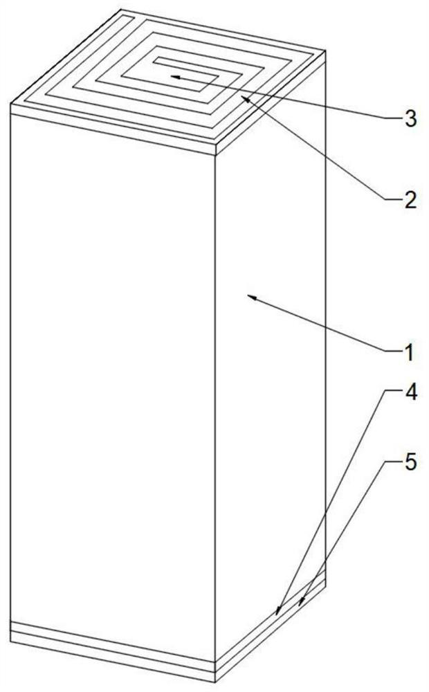
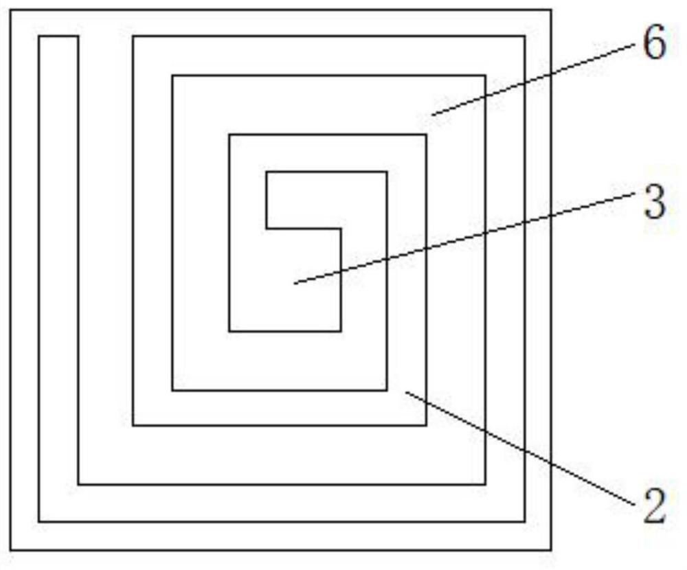
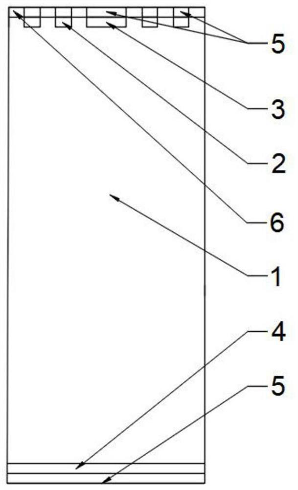
The invention discloses a spiral ring electrode silicon array detector, and relates to the technical field of radiation detection. The area of a spiral ring electrode of the detector is far smaller than that of a traditional whole-surface electrode, the leakage current and capacitance are smaller, the noise is small, and the energy resolution is high. According to existing processes, the pixel canbe in a micro-nano level, and the position resolution is very high; the detector can flexibly set a pressurization mode, the design of the spiral ring enables the electrode to have enough space to serve as a reading electrode or apply bias voltage. The detector comprises a cylindrical substrate, the top surface of the substrate is provided with a cathode jointly formed by a spiral ring electrodeformed by doping and a central electrode, and the central electrode is located in the center of the spiral ring electrode. The spiral ring electrode surrounds the central electrode, the number of spiral rings of the spiral ring electrode is K, K is a positive integer, and the bottom surface of the substrate is an anode formed by doping; and an electrode contact layer is arranged on the electrode on the top surface of the substrate, SiO2 covers the part without the electrode contact layer, and an electrode contact layer is arranged on the whole electrode on the bottom surface of the substrate.

Description

technical field [0001] The invention relates to the technical field of radiation detection, more specifically, it relates to a spiral ring electrode silicon array detector. Background technique [0002] Detectors are mainly used in high-energy physics, astrophysics, etc. Silicon detectors have high detection sensitivity, fast response, strong radiation resistance, and are easy to integrate. They have important application values ​​in high-energy particle detection and X-ray detection. . [0003] The silicon detector works under reverse bias. When external particles are incident on the sensitive area inside the detector, electron-hole pairs are generated under the action of an applied voltage, and the positive electrode collects the electrons that drift to the positive electrode, while the holes will The movement towards the negative pole is collected by the negative pole, and then an electrical signal reflecting particle information is output to an external circuit. [000...

Claims


Application Information

Patent Timeline
IPC IPC(8): H01L31/115H01L31/0352H01L31/0224
CPCH01L31/022416H01L31/0352H01L31/115
Inventor 刘曼文李正李鑫卿
Owner LUDONG UNIVERSITY
Learn More