Bidirectional new energy automobile charging pile with charging and discharging functions
A technology for new energy vehicles and charging piles, applied in electric vehicle charging technology, electric vehicles, charging stations, etc., can solve the problems of high current impact of vehicle batteries, danger to users, and short circuit of paint skin combustion, so as to avoid surface corrosion and use. Safety, the effect of reducing short-circuit phenomenon
- Summary
- Abstract
- Description
- Claims
- Application Information
AI Technical Summary
Problems solved by technology
Method used
Image
Examples
Embodiment 1
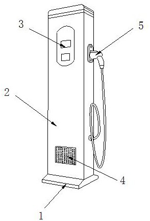
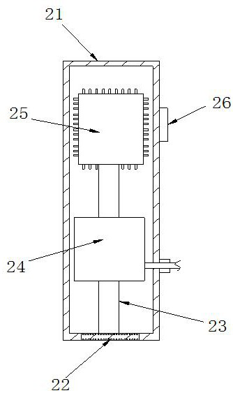
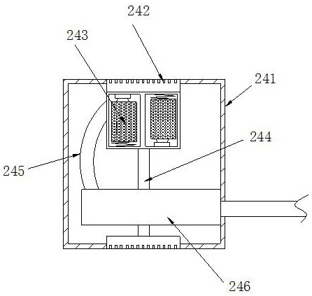
[0024] see Figure 1-Figure 4 , the specific embodiments of the present invention are as follows: a two-way new energy vehicle charging pile with charging and discharging functions, its structure includes a base 1, a body 2, an operating console 3, a heat dissipation port 4, and a charging head 5, and the top surface of the base 1 is connected to the The bottom surface of the body 2 is welded and connected, the back of the console 3 is fixedly installed on the front of the body 2, the outer layer of the heat dissipation port 4 is embedded in the front of the body 2, and the left side of the charging head 5 is superimposed on the right side of the body 2; The body 2 includes a casing 21, a charging bottom plate 22, a power transmission post 23, a cable structure 24, a processor 25, and a plug 26. The outer layer of the charging bottom plate 22 is embedded in the bottom of the casing 21, and the top surface of the charging bottom plate 22 passes through the charging post. 23 is ...
Embodiment 2
[0029] see Figure 5-Figure 7The specific embodiment of the present invention is as follows: the high-current circuit breaker A5 includes a fastening block A51, a sensing line A52, an electromagnet A53, a relay block A54, and a storage bin A55. The bottom of the fastening block A51 and the storage bin A55 are Integrated molding, the sensing line A52 is fixedly installed inside the fastening block A51, one side of the electromagnet A53 is embedded in the outer ring of the fastening block A51, the top of the relay block A54 is fixedly installed inside the fastening block A51, There are two relay blocks A54, and the two relay blocks A54 are symmetrically distributed on both sides of the inner ring of the fastening block A51, and are Y-shaped after being closed, which is conducive to increasing the contact area between the bottom surface and the transmission cable A6, and improving Transmission effect.
[0030] Wherein, the relay block A54 includes a block body B1, an output boar...
PUM
 Abstract
Description
Claims
Application Information
 - R&D
- Intellectual Property
- Life Sciences
- Materials
- Tech Scout
- Unparalleled Data Quality
- Higher Quality Content
- 60% Fewer Hallucinations
Browse by: Latest US Patents, China's latest patents, Technical Efficacy Thesaurus, Application Domain, Technology Topic, Popular Technical Reports.
© 2025 PatSnap. All rights reserved.Legal|Privacy policy|Modern Slavery Act Transparency Statement|Sitemap|About US| Contact US: help@patsnap.com


