
Cylindrical part rolling and liquid-filling deep-drawing forming device and method

A technology of liquid-filled deep drawing and cylindrical parts, which is applied in the field of metal processing, can solve the problems of easy cracking and wall thickness of cylindrical parts, low manufacturing precision of cylindrical parts, easy instability and wrinkling of flange area, etc., and achieves a solution The effect of low drawing limit, increasing forming limit, changing stress and strain state

Pending Publication Date: 2020-12-18
SHAOGUAN COLLEGE
View PDF0 Cites 0 Cited by
  • Summary
  • Abstract
  • Description
  • Claims
  • Application Information

AI Technical Summary

Problems solved by technology

[0003] However, due to the characteristics of the process itself, the friction between the mold and the metal sheet, especially the blankholder exerts a blankholding force on the sheet. If the pressure exerted by the blankholder is too small, the flange area is prone to instability and wrinkling
If the blank holder force is too large, the friction between the mold and the sheet is too large, restricting the flow of material from the flange area to the die, resulting in problems such as cracking and uneven wall thickness of the cylindrical part during the deep drawing process.
[0004] Therefore, for cylindrical parts with large drawing coefficient and large height-to-diameter ratio, the material flow is difficult and the deformation is uneven. Using traditional deep drawing requires multiple sets of molds for multiple drawing, resulting in low manufacturing accuracy of such cylindrical parts. , Increased production cost and extended production cycle

Method used


Image

  • Cylindrical part rolling and liquid-filling deep-drawing forming device and method
  • Cylindrical part rolling and liquid-filling deep-drawing forming device and method
  • Cylindrical part rolling and liquid-filling deep-drawing forming device and method

Examples


Embodiment Construction

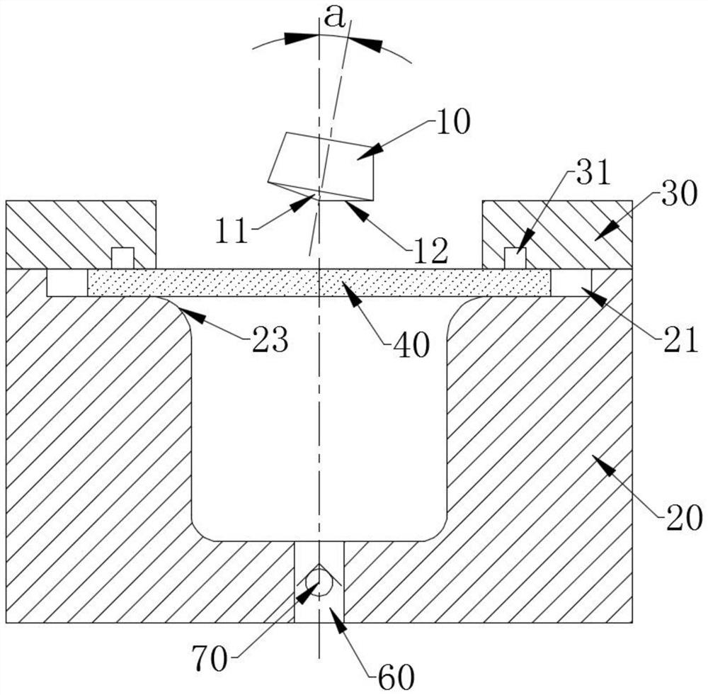
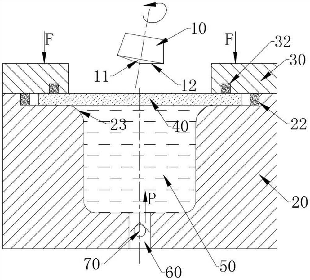
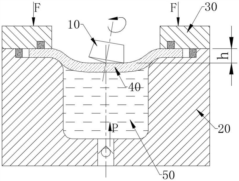
[0047] In order to solve the deficiencies and defects existing in the prior art, the present invention provides a device and method for rolling and filling liquid-filled deep-drawing of cylindrical parts, which applies partial deep-drawing to the sheet material by swinging the rolling punch, and then completes the overall drawing of the part. deep. During the deep drawing process, the liquid pressure is applied on the other side of the sheet to improve the stress state of the sheet, which can effectively improve the forming limit of the sheet and the forming quality of the parts, and save costs.

[0048] Such as Figure 1 to Figure 5 As shown, a rolling liquid-filled deep-drawing forming device for cylindrical parts includes a rolling punch 10 , a die 20 and a blank holder 30 .

[0049] Wherein, the blank holder 30 is movably arranged above the die 20, and the blank holder 30 is used to clamp the blank 40 to be formed between the blank holder 30 and the die 20. between.

[...


PUM


Abstract

The invention discloses a cylindrical part rolling and liquid-filling deep-drawing forming device. The cylindrical part rolling and liquid-filling deep-drawing forming device comprises a rolling maledie, a female die and a blank holder, and a conical rolling face is arranged at the end of the rolling male die; the rolling male die can move in the axial direction and the radial direction of an inner cavity of the female die and can rotate around the center axis of the rolling male die and the center axis of the inner cavity of the female die; and the female die is provided with a channel usedfor filling an inner cavity of the female die with a liquid medium, and the channel is provided with a liquid-filling valve. The invention further discloses a cylindrical part rolling and liquid-filling deep-drawing forming method which adopts the cylindrical part rolling and liquid-filling deep-drawing forming device to carry out deep-drawing forming on a plate. According to the cylindrical partrolling and liquid-filling deep-drawing forming device and method, local deep drawing is applied to the plate by swinging the rolling male die, and then overall deep drawing of a part is completed. Inthe deep drawing process, liquid pressure is applied to the other face of the plate, the stress state of the plate is improved, the forming limit of the plate and the forming quality of the part canbe effectively improved, and cost is saved.

Description

technical field [0001] The invention belongs to the technical field of metal processing, and in particular relates to a device and method for rolling, liquid-filled and deep-drawing of cylindrical parts. Background technique [0002] At present, the deep drawing process is used to manufacture metal cylindrical parts, which has the advantages of high productivity, high material utilization rate and low production cost, and is widely used in the fields of automobiles, instrumentation, electronics and aerospace. [0003] However, due to the characteristics of the process itself, the friction between the mold and the metal sheet, especially the blankholder exerts a blankholding force on the sheet. If the pressure exerted by the blankholder is too small, the flange area is prone to instability and wrinkling. If the blank holder force is too large, the friction between the mold and the sheet is too large, restricting the flow of material from the flange area to the die, resulting ...

Claims


Application Information

Patent Timeline
IPC IPC(8): B21D22/22B21D24/16B21D51/10
CPCB21D22/22B21D24/16B21D51/10
Inventor 陈名涛王刚郑铭智
Owner SHAOGUAN COLLEGE
Learn More