Full-automatic numerical control machine tool cutting fluid recycling equipment

A technology for CNC machine tools and cutting fluids, which is applied in metal processing equipment, maintenance and safety accessories, metal processing machinery parts, etc. It can solve the problems of low cutting fluid recovery efficiency, affecting the smooth circulation of cutting fluid, and clogging of filters. Ensure the filtering effect and smoothness, ensure smooth flow, and prevent the effect of filter clogging

Pending Publication Date: 2020-12-18
QILU UNIV OF TECH
View PDF0 Cites 6 Cited by
  • Summary
  • Abstract
  • Description
  • Claims
  • Application Information

AI Technical Summary

Problems solved by technology

[0003] In the production process of flat ceramic membranes, it is necessary to use CNC machine tools to process them. In order to save resources, the cutting fluid generated during the processing needs to be recycled and reused. At present, a filter is generally installed at the recycling end of the cutting fluid. When flowing down through the filter screen, the debris in the cutting fluid is retained above the filter screen, thereby realizing the filtration and recovery of the cutting fluid. However, there is a disadvantage of this filtering method, that is, the debris in the cutting fluid will gradually fade during long-term use. Accumulated on the mesh surface, causing filter blockage, thus affecting the smooth circulation of cutting fluid, resulting in low efficiency of cutting fluid recovery

Method used


Image

  • Full-automatic numerical control machine tool cutting fluid recycling equipment
  • Full-automatic numerical control machine tool cutting fluid recycling equipment
  • Full-automatic numerical control machine tool cutting fluid recycling equipment

Examples


Embodiment 1

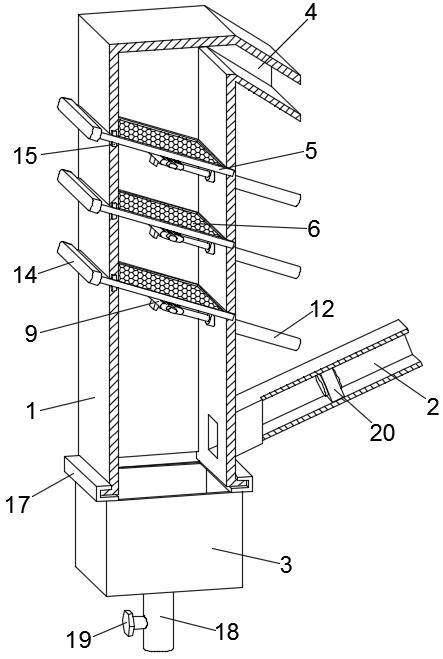
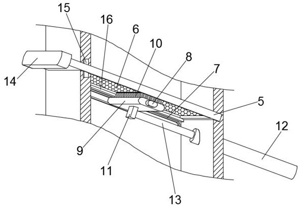
[0023] see Figure 1-2 , a fully automatic CNC machine tool cutting fluid recovery and utilization equipment, including a recovery bin 1, a recovery pipe 2 connected to one side of the lower end of the recovery bin 1, a chip collection box 3 at the bottom of the recovery bin 1, and a top of the recovery bin 1 There is a backflow port 4 on the side; several filter assemblies are arranged in the vertical direction in the recovery bin 1, and the filter assemblies include a sealing plate 5 and a filter screen 6, and the sealing plate 5 is inclined downward from the side wall of the recovery bin 1 It extends into the recovery bin 1 and is stuck on the inner wall of the opposite side of the recovery bin 1. A filter screen 6 is provided on the sealing plate 5, and a cleaning mechanism is provided below each filter assembly. The cleaning assembly includes a slide rail 7 and a mounting Plate 9, the slide rail 7 is fixedly installed on the inner wall of the recovery bin 1 and is consist...

Embodiment 2

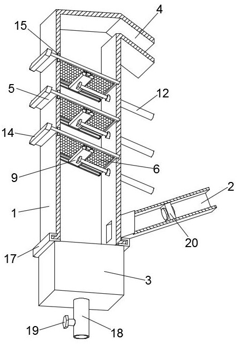
[0033]A fully automatic CNC machine tool cutting fluid recycling equipment, including a recovery bin 1, a recovery pipe 2 connected to the lower end of the recovery bin 1, a chip collection box 3 at the bottom of the recovery bin 1, and a top side of the recovery bin 1 A return port 4 is provided; several filter assemblies are arranged in the vertical direction in the recovery bin 1, and the filter assemblies include a sealing plate 5 and a filter screen 6, and the sealing plate 5 extends obliquely downward from the side wall of the recovery bin 1. into the recovery bin 1 and is clamped on the inner wall of the opposite side of the recovery bin 1, a filter screen 6 is provided on the sealing plate 5, and a cleaning mechanism is provided under each filter assembly, and the cleaning assembly includes a slide rail 7 and a mounting plate 9. The slide rail 7 is fixedly installed on the inner wall of the recovery bin 1 and is consistent with the inclination of the filter screen 6. A ...


PUM


Abstract

The invention discloses full-automatic numerical control machine tool cutting fluid recycling equipment. The equipment comprises a recovering bin, one side of the lower end of the recovering bin communicates with a recovering pipe, a scrap collecting box is arranged at the bottom of the recovering bin, a backflow opening is formed in one side of the top of the recovering bin, a plurality of filtering assemblies are arranged in the recovering bin in the vertical direction, and a removing mechanism is arranged below each filtering assembly. According to the full-automatic numerical control machine tool cutting fluid recycling equipment, a cutting fluid is injected from the bottom of the recovering bin and then flows out from the top, firstly automatic sedimentation is achieved through the gravity of scraps, so that most scraps are collected, scraps mixed in the cutting fluid are filtered step by step through the multiple layers of filtering assemblies, so that the quality of the recovered cutting fluid is guaranteed, meanwhile, filter screens can be effectively prevented from being blocked, smooth flowing of the cutting fluid is guaranteed, and the recovering efficiency is improved,and the removing mechanisms are arranged below the filter screens, so that holes of the filter screens are prevented from being blocked, and the filtering effect and smoothness of the filter screens are guaranteed.

Description

technical field [0001] The invention relates to the technical field of production and processing of flat ceramic membranes, in particular to a fully automatic CNC machine tool cutting fluid recovery and utilization device. Background technique [0002] Ceramic membrane has many advantages such as good chemical stability, acid and alkali resistance, organic solvent resistance, high temperature resistance, pollution resistance, high mechanical strength and long service life, and has been successfully applied in water treatment, food processing, biomedicine and fine chemical industry, etc. It can be used in the process of separation, clarification, purification and concentration in the process. Among them, the flat ceramic membrane has many advantages such as low manufacturing cost, small filtration resistance, low energy consumption, strong anti-pollution ability and easy cleaning, so it has been rapidly developed and expanded in recent years. [0003] In the production proce...

Claims


Application Information

Patent Timeline
Patent Type & Authority Applications(China)
IPC IPC(8): B23Q11/10
CPCB23Q11/1069
Inventor 毕延刚
Owner QILU UNIV OF TECH
Why Eureka
Try Eureka