A data center bus hard-connected plug-in device

A technology for data centers and plug-in devices, which is applied in the direction of fully enclosed busbar devices, parts and connections of connecting devices, etc., can solve the problems of unreliable contact pressure, limited spring life, easy spring failure, etc., to achieve the current carrying capacity and heat dissipation. The effect of high area, reduced temperature rise and heat generation, and reliable and stable installation structure

Active Publication Date: 2021-11-30
ZHENJIANG GARDERMOEN INTELLIGENT POWER TECH CO LTD
View PDF4 Cites 0 Cited by
  • Summary
  • Abstract
  • Description
  • Claims
  • Application Information

AI Technical Summary

Problems solved by technology

[0003] In the prior art, the socket housing of the data center busbar plug-in device generally uses a spring to control the stroke of the pin terminal. When the protruding pin terminal touches the busbar, the spring is squeezed and compressed, and the elastic restoring force of the spring will connect the pin terminal with the busbar. Compression contact, while the plug terminal and the busbar are a contact point, the current carrying capacity and heat dissipation area are small, and the temperature rise is high at the same time. After long-term use, the spring is difficult to load and the pin is connected to electricity. High temperature leads to burnout, and the life of the spring itself Limited lead to gradual loss of elasticity, resulting in easy failure of the spring, unreliable contact pressure, resulting in poor contact between the plug terminal and the busbar, causing power outage, thus affecting the normal operation of the busbar in the data center

Method used


Image

  • A data center bus hard-connected plug-in device
  • A data center bus hard-connected plug-in device
  • A data center bus hard-connected plug-in device

Examples


Embodiment Construction

[0023] The specific embodiments of the present invention will be further described below in conjunction with the accompanying drawings.

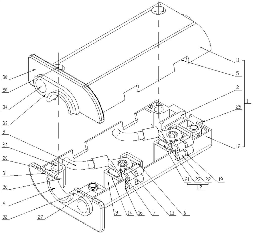
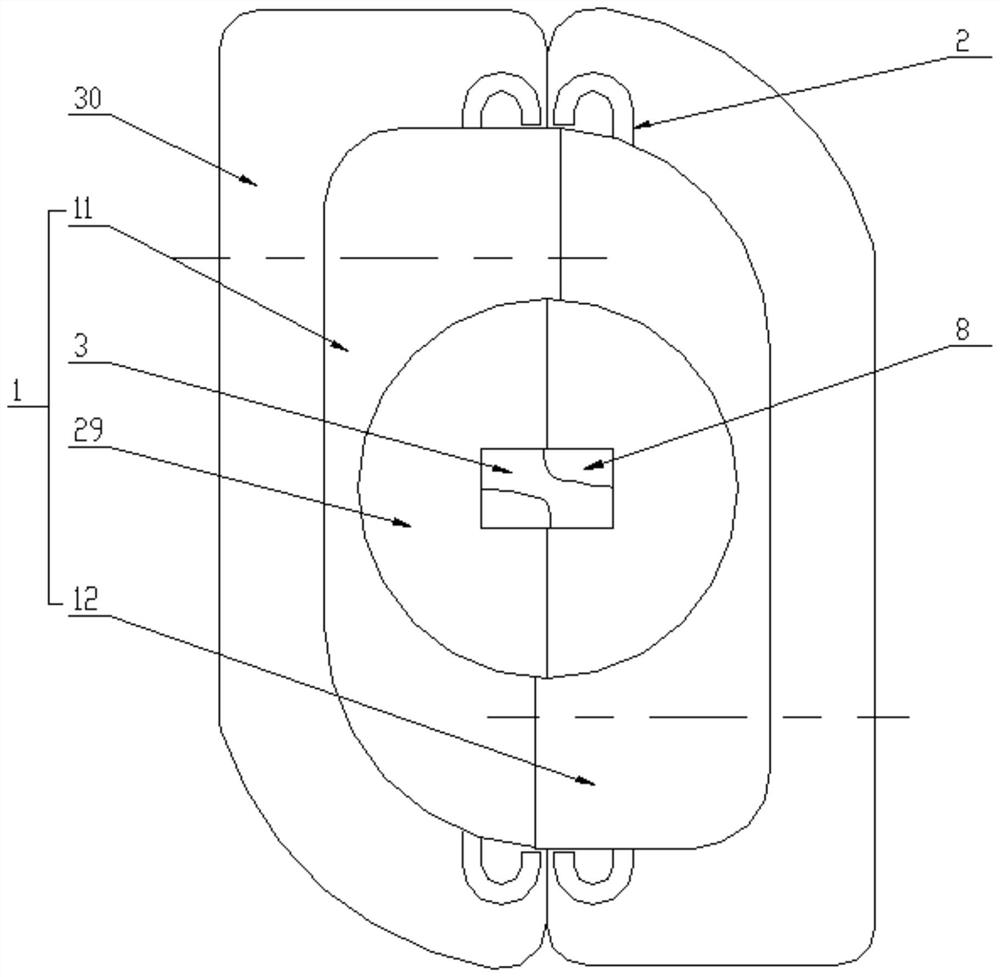
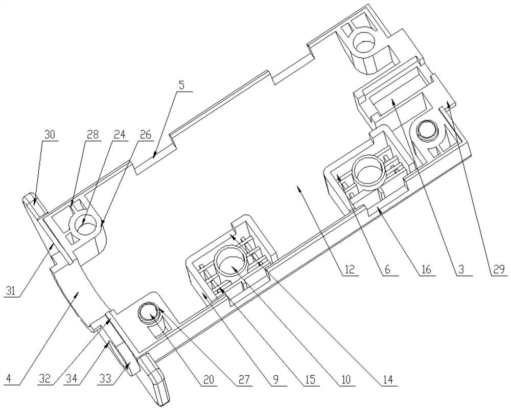
[0024] A data center busbar hard-connected plug-in device, including a plug-in housing 1, phase wire terminals 2 are provided on both sides of the plug-in housing 1, and PE terminal slots are respectively provided at both ends of the plug-in housing 1 3 and wiring holes 4, wherein, the socket housing 1 includes a left housing 11 and a right housing 12 that are consistent in structure and connected in opposite directions, and the left housing 11 and the right housing 12 are provided on the same side The first notch 16 or the second notch 5 corresponding to the first notch 16, the side of the first notch 16 or the second notch 5 is provided with a mounting groove 6, and the phase line terminal 2 is arranged on In the installation groove 6 and on the top, there is a copper nose 7 connected to the left housing 11 or the right housing 12, and the...


PUM


Abstract

The invention relates to a data center busbar hard-connected plugging device, which includes a plugging case, phase wire terminals are arranged on both sides of the plugging case, and PE terminal slots and wiring holes are respectively provided at both ends of the plugging case. The socket housing includes a left housing and a right housing that are consistent in structure and connected to each other. The left housing and the right housing are provided with a first notch or a second notch corresponding to the first notch on the same side. The phase wire terminal is set in the installation groove on the side of the first notch or the second notch, and the top is provided with a copper nose connected to the left or right housing, and the end of the phase wire terminal protrudes from the socket housing , and it is a U-shaped structure with the ends facing inwards, the contact surface between the phase line terminal and the busbar is larger, the current carrying capacity and the heat dissipation area are higher, which can effectively reduce the temperature rise and heat generation, and the 90°rotatable socket housing The phase line terminal and the data center bus bar are hard-connected for conduction, avoiding the problem of spring failure, and improving the safety, stability and power distribution and transmission performance of the data center bus power distribution and plugging during long-term operation.

Description

technical field [0001] The invention relates to a data center bus hard connection plugging device, which belongs to the technical field of data center bus power distribution. Background technique [0002] With the emergence of modern engineering facilities and equipment, the power consumption of all walks of life is increasing rapidly, especially the emergence of many high-rise buildings and large workshops. As an important power distribution system, the data center bus system is widely used in automobiles, metallurgy, Electronics, petrochemical, commercial, real estate and other industries have the characteristics of plugging and distributing power at any position on the opening side of the bus duct. Through the power distribution tap of the plug-in device and the busbar of the data center, the power is connected to the cable power distribution device. Realize system configuration, so the power connection performance of the plug-in device directly affects the safety, stabil...

Claims


Application Information

Patent Timeline
Patent Type & Authority Patents(China)
IPC IPC(8): H01R13/502H01R13/42H01R13/22H02G5/06H02G5/08
CPCH01R13/22H01R13/42H01R13/502H02G5/06H02G5/08
Inventor 马见雄李广卿胡桥宇朱恩元方加明
Owner ZHENJIANG GARDERMOEN INTELLIGENT POWER TECH CO LTD
Why Eureka
Try Eureka