Injection lens automatic dyeing machine

A dyeing machine and lens technology, applied in the direction of liquid cleaning methods, coatings, cleaning methods and utensils, etc., can solve the problems of high labor intensity for operators, difficult control of environmental humidity, and impact on product quality, so as to eliminate production safety Hidden dangers, realization of dyeing automation, and the effect of reducing labor intensity of workers

Active Publication Date: 2021-12-03
艾普光学科技(厦门)有限公司
View PDF19 Cites 0 Cited by
  • Summary
  • Abstract
  • Description
  • Claims
  • Application Information

AI Technical Summary

Problems solved by technology

[0003] The existing injection lens dyeing process is completed by a single point and a single machine. The machines in each production link are independent and separated, and can only be connected by manual handling. The entire dyeing process requires a lot of manpower. The cost is high, the labor intensity of the operators is also high, the production efficiency is low, and the water and dyeing solution for rinsing the lens during the dyeing process are easy to spill on the floor, resulting in slippery floors, high humidity in the workshop, and difficult control of environmental humidity, which affects product quality. And because the ground is wet and slippery, it is easy to cause the operator to slip and fall, which poses a safety hazard

Method used


Image

  • Injection lens automatic dyeing machine
  • Injection lens automatic dyeing machine
  • Injection lens automatic dyeing machine

Examples


Embodiment Construction

[0055] In order to make the purpose, features and advantages of the present invention more comprehensible, specific implementations of the present invention will be described in detail below in conjunction with the accompanying drawings.

[0056] It should be noted that the terms "front", "rear", "left", "right", "upper", "lower", "first", "second" and similar expressions used herein are for illustrative purposes only It is not intended to indicate or imply that the device or element referred to must have a specific orientation, be constructed and operate in a specific orientation, and thus should not be construed as limiting the invention.

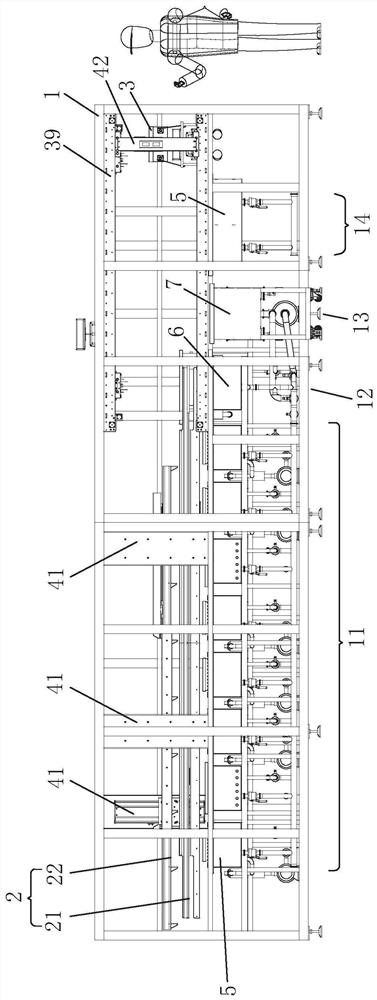
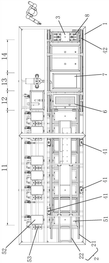
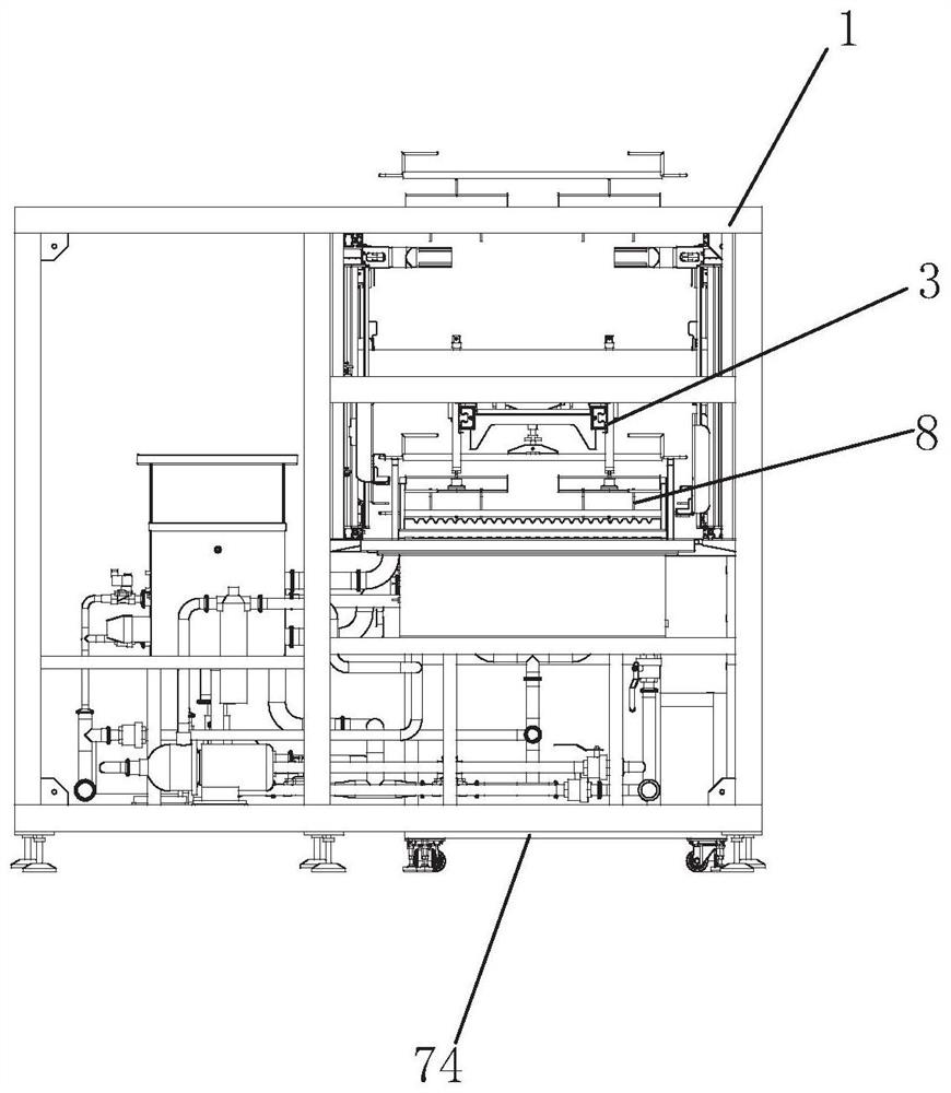
[0057] Such as Figure 1 to Figure 16 As shown, the injection molding lens automatic dyeing machine disclosed by the present invention includes a frame 1, a transmission mechanism 2, a grasping mechanism 3, a lifting mechanism (divided into a first lift 41 and a second lift 42), a cleaning mechanism 5, and a water cutting mechanism 6. Dy...


PUM


Abstract

The invention discloses an automatic dyeing machine for injection molding lenses, which comprises a frame, a transmission mechanism, a grasping mechanism, a lifting mechanism, a cleaning mechanism, a water cutting mechanism, a dyeing mechanism, a lens fixture and a programmable controller; a first cleaning area is formed in the frame , the water cutting area, the dyeing area and the second cleaning area; the lens fixture is set in the first cleaning area and the water cutting area through the cooperation of the transmission mechanism and the lifting mechanism, and is also set in the water cutting area and the water cutting area through the cooperation of the grabbing mechanism and the lifting mechanism. The dyeing area and the second cleaning area; the water cutting mechanism keeps the lens fixture in a static state during water cutting. During the water cutting process, the lens is still, and the water is cut by the water flow rising first and then falling to make the water cutting more thorough; the dyeing mechanism can cooperate with The dyeing car is assembled with the main dyeing tank and the dyeing auxiliary tank, so as to move the rack to replace the dyeing solution. The invention can realize the automation of the lens dyeing process, improve the dyeing efficiency of the lens, and improve the quality of the dyed lens.

Description

technical field [0001] The invention relates to the technical field of sun lens manufacturing, in particular to an injection molding lens automatic dyeing machine. Background technique [0002] The so-called lens tinting is to add some chemical substances during the lens manufacturing process to make the lens appear colored to absorb light of a specific wavelength. The process of lens dyeing generally includes: pre-treatment, cleaning, dehydration, dyeing and rinsing. [0003] The existing injection lens dyeing process is completed by a single point and a single machine. The machines in each production link are independent and separated, and can only be connected by manual handling. The entire dyeing process requires a lot of manpower. The cost is high, the labor intensity of the operators is also high, the production efficiency is low, and the water and dyeing solution for rinsing the lens during the dyeing process are easy to spill on the floor, resulting in slippery floo...

Claims


Application Information

Patent Timeline
Patent Type & Authority Patents(China)
IPC IPC(8): B05C3/09B05C13/02B08B3/12B08B3/14B05C11/10
CPCB05C3/09B05C11/10B05C11/1042B05C13/02B08B3/12B08B3/14
Inventor 范泽旺王旭静
Owner 艾普光学科技(厦门)有限公司
Why Eureka
Try Eureka