Movable combined cycle power generation system

A technology for combined cycle power generation and power generation sub-systems, applied in the direction of combined combustion mitigation, electromechanical devices, electrical components, etc., can solve the problems of low power generation efficiency of mobile power generation systems, and the power generation efficiency is difficult to exceed 20%. Effects of mobility, improved energy efficiency, and increased power generation efficiency

Pending Publication Date: 2020-12-22
HARBIN INST OF TECH
View PDF0 Cites 4 Cited by
  • Summary
  • Abstract
  • Description
  • Claims
  • Application Information

AI Technical Summary

Problems solved by technology

Restricted by the size and weight of equipment, the power generation of mobile power generation systems is generally at the level of hundreds of kilowatts, and because the operating temperature and pressure of mobile power generation systems are much lower than those of fixed power generation systems, this has led to the development of mobile power generation systems. The power generation efficiency is very low, and the power generation efficiency of each mobile power generation system is difficult to exceed 20% under simple cycle conditions

Method used


Image

  • Movable combined cycle power generation system
  • Movable combined cycle power generation system
  • Movable combined cycle power generation system

Examples


Embodiment Construction

[0033] It should be noted that, in the case of no conflict, the embodiments of the present invention and the features in the embodiments can be combined with each other.

[0034] The invention will be described in detail below with reference to the accompanying drawings and examples.

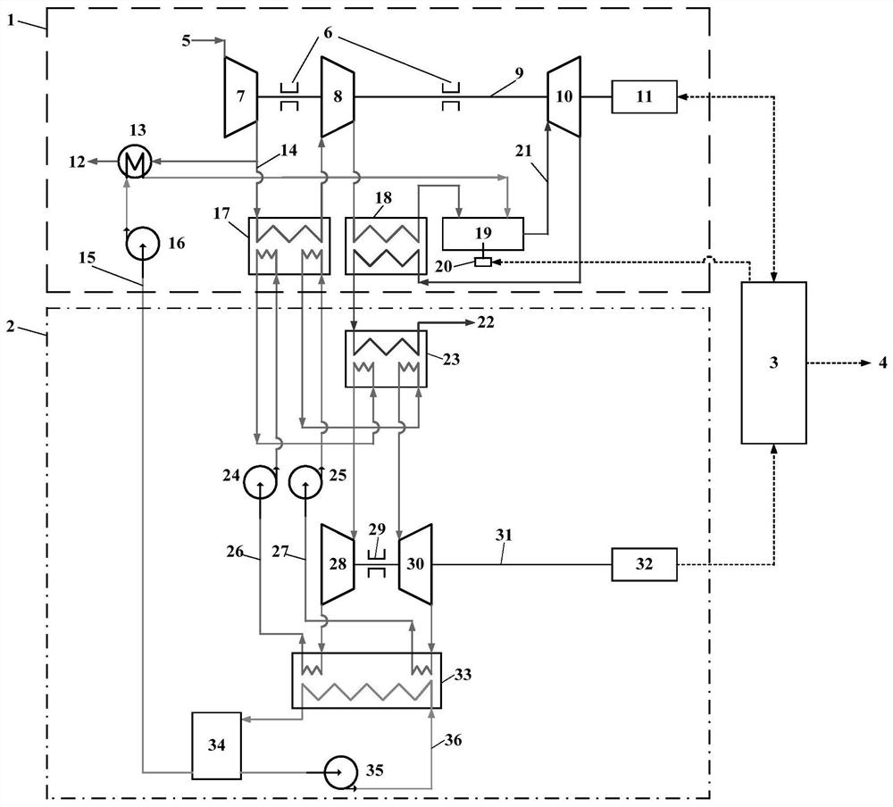
[0035] Such as figure 1As shown, a mobile combined cycle power generation system includes a single-stage micro gas turbine power generation sub-system 1, a two-stage organic Rankine cycle power generation sub-system 2 and a battery pack 3, and the single-stage micro gas turbine power generation sub-system 1 includes Stage I compressor 7, Stage II compressor 8, combustion chamber 19, turbine 10, regenerator 18, heat exchanger one 13, heat exchanger two 17, air-cooled generator one 11, rotor one 9 and fuel pump 16 The two-stage organic Rankine cycle power generation subsystem includes a first-stage drive pump 24, a second-stage drive pump 25, a first-stage circulating working medium 26, a second-...


PUM


Abstract

The invention provides a movable combined cycle power generation system which comprises a single-stage micro gas turbine power generation subsystem, a double-stage organic Rankine cycle power generation subsystem and a battery pack, wherein the single-stage micro gas turbine power generation subsystem comprises a first-stage gas compressor, a second-stage gas compressor, a combustion chamber, a turbine, a heat regenerator, a first heat exchanger, a second heat exchanger, a first air cooling generator, a first rotor and a fuel pump; the two-stage organic Rankine cycle power generation subsystemcomprises a first-stage drive pump, a second-stage drive pump, a first-stage cycle working medium, a second-stage cycle working medium, an evaporator, a first-stage expansion machine, a second-stageexpansion machine, a condenser, a condensation pump, a fuel tank, a second rotor and a second air cooling power generator; and the first air cooling generator and the second air-cooled generator supply power to the battery pack, and the battery pack supplies power to a power utilization side. The system provided by the invention has the advantages of simple flow, high integration, convenience in operation, wide adjustment range and low pollutant emission, and can improve power generation efficiency for different fuels and environmental conditions.

Description

technical field [0001] The invention belongs to the technical field of power generation, and in particular relates to a movable combined cycle power generation system. Background technique [0002] Electric energy is a high-order energy in energy cascade utilization, and improving power generation efficiency is the goal pursued by every power generation system. Restricted by the size and weight of equipment, the power generation of mobile power generation systems is generally at the level of hundreds of kilowatts, and because the operating temperature and pressure of mobile power generation systems are much lower than those of fixed power generation systems, this has led to the development of mobile power generation systems. The power generation efficiency is very low, and the power generation efficiency of each mobile power generation system is difficult to exceed 20% under simple cycle conditions. Therefore, in view of the lower operating temperature and pressure conditio...

Claims


Application Information

Patent Timeline
Patent Type & Authority Applications(China)
IPC IPC(8): F02C6/00F02C3/04F01K23/10F01K11/02F01D15/10F04D25/16F23R3/12F23R3/28H02K7/18
CPCF01D15/10F01K11/02F01K23/10F02C3/04F02C6/00F04D25/16F23R3/12F23R3/28H02K7/1807Y02E20/16
Inventor 邢畅刘栗邱朋华沈闻凯陈希叶张林瑶吕亚锦胡启明刘健卢成
Owner HARBIN INST OF TECH
Why Eureka
Try Eureka