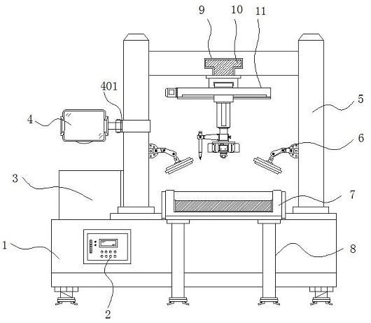
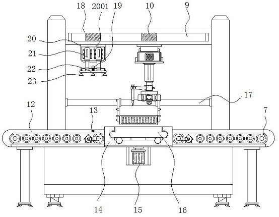
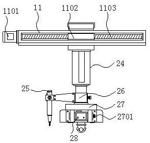
Visual inspection equipment capable of identifying flaws for large part inspection

A large-scale parts and visual inspection technology, applied in the field of visual inspection, can solve problems such as low precision, inability to mark defects, false detection, etc., and achieve the effect of improving automation, efficiency and accuracy

Inactive Publication Date: 2020-12-22
CHONGQING TECH & BUSINESS UNIV
View PDF0 Cites 11 Cited by
  • Summary
  • Abstract
  • Description
  • Claims
  • Application Information

AI Technical Summary

Problems solved by technology

[0002] Visual inspection is to use machines instead of human eyes for measurement and judgment. In some dangerous working environments that are not suitable for manual work or where artificial vision is difficult to meet the requirements, machine vision is often used to replace artificial vision; at the same time, in mass industrial production processes Among them, using artificial vision to check product quality is low in efficiency and accuracy, and machine vision inspection methods can greatly improve production efficiency and production automation. more widely used
[0003] At present, some large-scale factories use visual inspection equipment to detect parts. For large parts, generally defective products will not be discarded directly, but need to be reworked. The alarm reminds employees to take away the defective product, but it cannot mark the defective part at the same time as the detection. Since the defect of each part may be different, employees often only know that the part has a defect when reworking later, but they cannot immediately know the defect. The specific location and quantity, so it needs to be manually checked again before rework can be reworked, the accuracy is poor, and the probability of missed detection and false detection is also high

Method used


Image

  • Visual inspection equipment capable of identifying flaws for large part inspection
  • Visual inspection equipment capable of identifying flaws for large part inspection
  • Visual inspection equipment capable of identifying flaws for large part inspection

Examples


Embodiment Construction

[0025] The following will clearly and completely describe the technical solutions in the embodiments of the present invention with reference to the accompanying drawings in the embodiments of the present invention. Obviously, the described embodiments are only some, not all, embodiments of the present invention.

[0026] In the description of the present invention, unless otherwise stated, the meaning of "plurality" is two or more; the terms "upper", "lower", "left", "right", "inner", "outer" , "front end", "rear end", "head", "tail", etc. indicate the orientation or positional relationship based on the orientation or positional relationship shown in the drawings, and are only for the convenience of describing the present invention and simplifying the description, rather than Indicates or implies that the device or element referred to must have a particular orientation, be constructed and operate in a particular orientation, and therefore should not be construed as limiting the...


PUM


Abstract

The invention discloses visual inspection equipment capable of identifying flaws for large part inspection. Particularly, the equipment comprises a workbench, a feeding mechanism, an oily pen and a CCD camera, a computer operation room is arranged in the middle of one end of the top of the workbench, and a frame body is arranged at the other end of the top of the workbench; a feeding conveying belt is fixed to one side of the top of the workbench through an installation frame, and a photoelectric sensor is installed on the side, close to the feeding conveying belt, of the interior of the feeding conveying belt. The visual detection equipment capable of identifying flaws for large part detection is provided with a transverse electromagnetic sliding rail, a longitudinal guide rail, a hydraulic lifting rod and the oily pen. The oil pen can move to the flaws of the part under the synergistic effect of the transverse electromagnetic sliding rail, the longitudinal guide rail and the hydraulic lifting rod to draw circles and mark the detected flaws, follow-up rework of workers is facilitated, and the rework efficiency and accuracy are improved.

Description

technical field [0001] The invention relates to the technical field of visual inspection, in particular to a visual inspection device capable of marking defects for inspection of large parts. Background technique [0002] Visual inspection is to use machines instead of human eyes for measurement and judgment. In some dangerous working environments that are not suitable for manual work or where artificial vision is difficult to meet the requirements, machine vision is often used to replace artificial vision; at the same time, in mass industrial production processes Among them, using artificial vision to check product quality is low in efficiency and accuracy, and machine vision inspection methods can greatly improve production efficiency and production automation. The wider the application. [0003] At present, some large-scale factories use visual inspection equipment to detect parts. For large parts, generally defective products will not be discarded directly, but need to ...

Claims


Application Information

Patent Timeline
Patent Type & Authority Applications(China)
IPC IPC(8): G01N21/88G01N21/13
CPCG01N21/13G01N21/8806G01N2021/8835G01N2021/8883
Inventor 喻其炳张华华孔丽杰
Owner CHONGQING TECH & BUSINESS UNIV
Why Eureka
Try Eureka