
Electric heating washing type waste gas treatment device

A waste gas treatment device, electric heating device technology, applied in the direction of combined devices, lighting and heating equipment, combustion methods, etc., can solve the problems of reducing the concentration, easy to get stuck in the scraper, uncontrollable liquid level, etc., to reduce the chance of entering the water tank , improve processing efficiency and avoid water pump damage

Pending Publication Date: 2020-12-25
武汉更日敦科技有限公司 +2
View PDF1 Cites 5 Cited by
  • Summary
  • Abstract
  • Description
  • Claims
  • Application Information

AI Technical Summary

Problems solved by technology

However, there are still many shortcomings in this prior art, for example: 1. During use, fresh water is always discharged and waste water is discharged, and the water consumption is large; It is easy to get stuck and difficult to maintain; 3. Double scrubbers are used, which is costly and the equipment has large dimensions; 4. The second scrubber reduces the concentration of gas after treatment by introducing external air to mix, and it is difficult to judge the equipment's effectiveness against harmful gases. Treatment efficiency; 5. The crystals are scraped off by a scraper and fall into the water tank, which is easy to deposit and scale, and cannot be effectively discharged; 6. The process of high-temperature gas entering the second scrubber after thermal cracking will cause the temperature of the water tank and the pipeline passing through to be biased. High; 7. When the liquid level gauge at the high water level fails or is damaged, the liquid level is uncontrollable

Method used


Image

  • Electric heating washing type waste gas treatment device
  • Electric heating washing type waste gas treatment device
  • Electric heating washing type waste gas treatment device

Examples


Embodiment Construction

[0049] The specific technical solutions of the present invention will be described in detail below through examples. It should be noted that the following examples can only be used to explain the technical solutions of the present invention and should not be construed as limitations on the present invention.

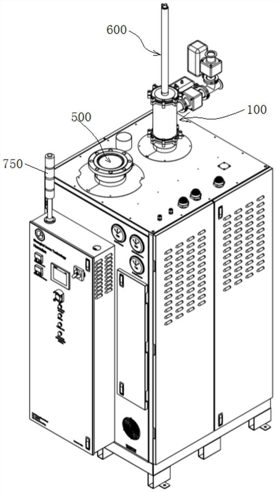
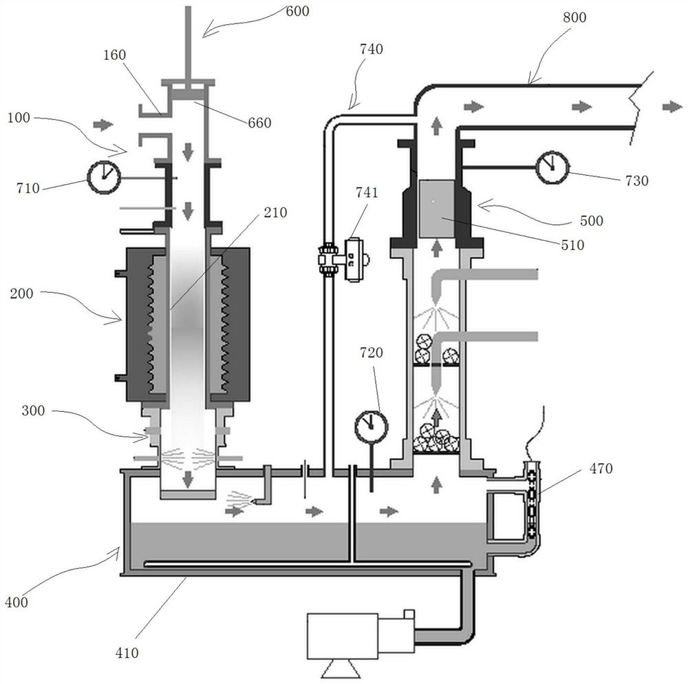
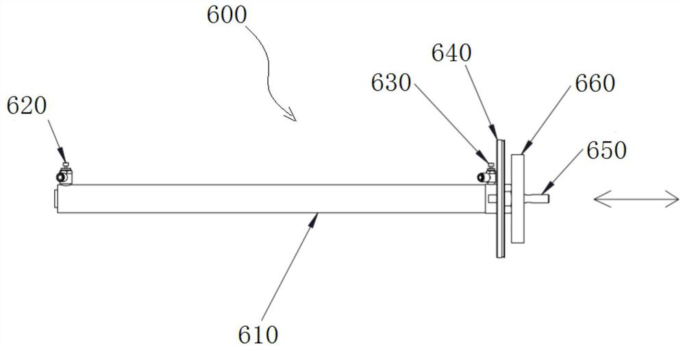
[0050] like figure 1 As shown, it is a schematic diagram of the appearance of an embodiment of the electric heating water washing waste gas treatment device of the present invention, as figure 2 As shown, it is a schematic structural diagram of an embodiment of the electric heating water washing waste gas treatment device of the present invention. The electric heating water washing waste gas treatment device includes a first air inlet 100, an electric heating device 200, a dust filter device 300, an intelligent cooling water washing System 400 and air outlet 500, the first air inlet 100 is arranged on the electric heating device 200, the electric heating device 200 is a...


PUM

PropertyMeasurementUnit
pore sizeaaaaaaaaaa

Abstract

The invention relates to an electric heating washing type waste gas treatment device which comprises a first gas inlet, an electric heating device, a dust filtering device, an intelligent cooling water washing system and a gas outlet, the first gas inlet is formed in the electric heating device, and the electric heating device is arranged on the dust filtering device; the dust filtering device isarranged at the upper part of a water tank of the intelligent cooling water washing system; and the combustion chamber scaling removing device is arranged on the tee joint at the upper part of the first air inlet, is provided with a stainless steel brush, can reach the interior of the combustion chamber of the electric heating device and brushes away dust on the inner wall of the combustion chamber. According to the invention, silane dust adhered to the inner wall of the combustion cavity can be automatically cleaned at regular time; the water consumption of fresh water is reduced, and the operation cost is reduced; the low water level, the high water level and the ultrahigh water level in the water tank are controlled through the four floaters, and the safety performance of equipment in use is improved; a four-stage spraying system is adopted, so that the waste gas treatment efficiency is improved.

Description

technical field [0001] The invention belongs to the field of waste gas treatment in the technical fields of semiconductor, solar energy, thin film battery, TFT, etc., and specifically relates to an electric heating water washing type waste gas treatment device. Background technique [0002] Process waste gas treatment equipment belongs to both the environmental protection industry and high-end intelligent auxiliary equipment for emerging industries such as semiconductors. In the manufacturing process of integrated circuits, some of the process modules (Module) such as: chemical vapor deposition (CVD), etching (Etch), ion implantation (Implant) and diffusion (Diffusion), and amorphous silicon thin film solar energy , PECVD process of liquid crystal TFT-LCD film, etc. will use a lot of special gases. After these gases participate in the process reaction, they are discharged in the form of waste gas, which can be divided into: Toxic, Acid, Alkali, Self-ignitable, Flammable, Co...

Claims


Application Information

Patent Timeline
Patent Type & Authority Applications(China)
IPC IPC(8): B01D50/00B01D53/18F23G7/06F23J1/00F23J15/06
CPCB01D53/185B01D53/1406B01D53/1412B01D53/18F23G7/06F23J1/00F23J15/06F23G2209/14B01D50/60
Inventor 郭海蓉胡建亮唐雄季永坚周和武钟建黄高明顾一峰陈昕红
Owner 武汉更日敦科技有限公司
Learn More