Multi-channel DDS chip substrate packaging structure and method

A packaging structure, multi-channel technology, applied in the direction of circuits, electrical solid-state devices, semiconductor devices, etc., can solve the problems of serious signal attenuation and low transmission channel isolation of multi-channel chips

Active Publication Date: 2020-12-25
CHENGDU CORPRO TECH CO LTD
View PDF7 Cites 5 Cited by
  • Summary
  • Abstract
  • Description
  • Claims
  • Application Information

AI Technical Summary

Problems solved by technology

[0007] The main purpose of the present invention is to provide a multi-channel chip substrate packaging structure and method, aiming to solve the problem of increasing mu

Method used


Image

  • Multi-channel DDS chip substrate packaging structure and method
  • Multi-channel DDS chip substrate packaging structure and method
  • Multi-channel DDS chip substrate packaging structure and method

Examples


Embodiment Construction

[0041] It should be understood that the specific embodiments described here are only used to explain the present invention, not to limit the present invention.

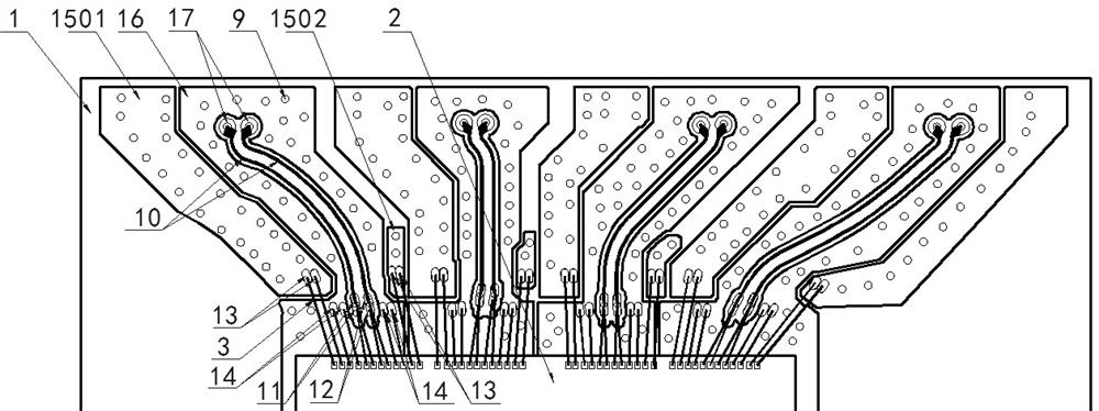
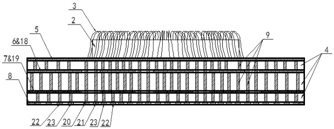
[0042] In this embodiment, a substrate package structure applied to a multi-channel DDS is provided, the structure has the requirements for the length, width, thickness, and direction of the multi-channel differential pair printed wiring path, the layout of the printed power ground plane, and The bonding fingers and leads of each signal are reasonably designed. The differential pair printed lines adopt an arc-shaped routing method, and the routing directions of the differential pair printed lines of each channel are not parallel to each other, and the printed ground plane is laid in the horizontal direction of the differential pair printed lines. The printed power plane is laid in the horizontal direction of the plane, the printed ground plane is laid on the next metal layer of the differential pair printed wiring, an...


PUM

PropertyMeasurementUnit
Line widthaaaaaaaaaa
Line spacingaaaaaaaaaa
Thicknessaaaaaaaaaa

Abstract

The invention discloses a multi-channel DDS (Direct Digital Synthesizer) chip substrate packaging structure and method, which are used for designing wiring of multi-channel differential pair signals,layout of a power supply ground plane and arrangement of bonding fingers and leading-out ends. The differential pair of each channel adopts an arc-shaped routing and non-parallel routing mode; power supply ground planes are laid in the horizontal direction, the lower layer and the lower layer of the differential pair, the power supply ground planes of all the channels are independent of one another and keep a certain isolation distance, crosstalk and coupling between the power supply ground planes of all the channels are reduced, signal loss of the multi-channel DDS chip is remarkably reduced,and isolation between all transmission channels is improved. The technical problems that in the prior art, attenuation of multi-channel DDS chip signals is increasingly serious, and the isolation degree between transmission channels is increasingly low are solved.

Description

technical field [0001] The invention relates to the technical field of integrated circuit packaging, in particular to a multi-channel DDS chip substrate packaging structure and method. Background technique [0002] Direct Digital Synthesizer (Direct Digital Synthesizer, DDS) is an important part of the modern radar signal source, and its technical index directly affects the performance of the radar system. Compared with traditional frequency synthesis methods, DDS synthesis technology, as a new frequency synthesis technology, has many advantages such as high frequency resolution, high frequency stability and fast frequency agility, and is widely used in multi-radar, electronic communication system. [0003] Direct digital frequency synthesis technology is a digital frequency synthesis chip. In order to improve system integration, it is often necessary to integrate multiple DDS cores in a single chip to form a multi-channel DDS. However, the high integration of multi-channe...

Claims


Application Information

Patent Timeline
IPC IPC(8): H01L23/49H01L23/66H01L21/60H05K1/11
CPCH01L24/49H01L24/48H01L23/66H01L24/85H05K1/115H01L2223/6611H01L2223/6616H01L2224/49174H01L2224/48229H01L2224/48227H01L2224/05554
Inventor 单国峰何善亮
Owner CHENGDU CORPRO TECH CO LTD
Why Eureka
Try Eureka