Supercharge Your Innovation With Domain-Expert AI Agents!

Direct-bonded lamination for improved image clarity in optical devices

A direct bonding and bonding technology, applied in optical components, optics, instruments, etc., can solve the problems of complex harmful effects of adhesive layers, and achieve the effect of eliminating dark line of sight, high image brightness, and less light scattering

Active Publication Date: 2020-12-25
隔热半导体粘合技术公司
View PDF10 Cites 0 Cited by
  • Summary
  • Abstract
  • Description
  • Claims
  • Application Information

AI Technical Summary

Problems solved by technology

The detrimental effects of traditional adhesive layers are compounded by the fact that the light path traverses many laminated optical components

Method used


Image

  • Direct-bonded lamination for improved image clarity in optical devices
  • Direct-bonded lamination for improved image clarity in optical devices
  • Direct-bonded lamination for improved image clarity in optical devices

Examples


Embodiment Construction

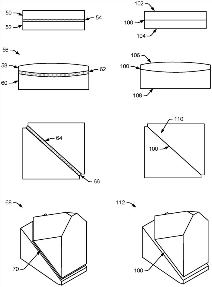
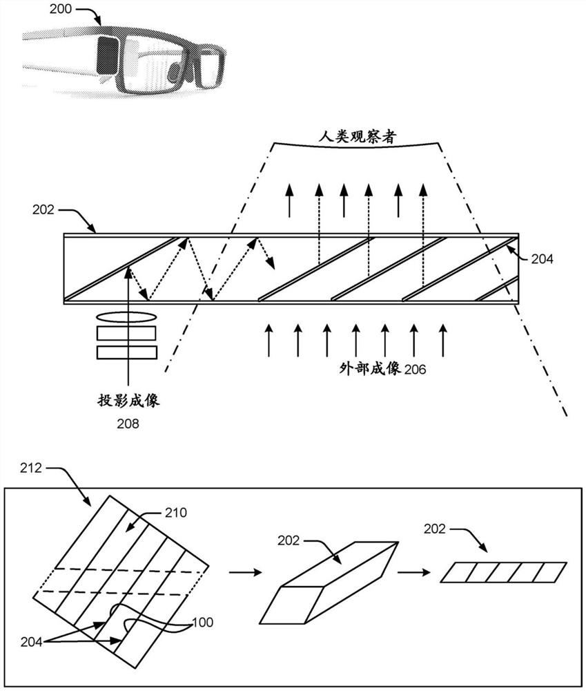
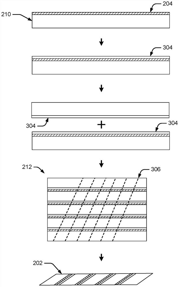
[0012] The present disclosure describes direct bond lamination for improved clarity in optical devices. In one implementation, the example direct bonding technique aims to minimize or eliminate optical adhesives and glues between optical layers that can lead to loss of image quality in the optical device.

[0013] In one implementation, for optical precision, bonding or lamination is done using direct oxide bonding between surfaces (such as silicon oxide to silicon oxide bonding) or direct bonding between surfaces and other semiconductor non-metallic combinations. An optical layer made of glass or other material. Besides silicon dioxide, other materials can also be used for direct bonding, such as silicon nitride (Si 3 N 4 ), silicon oxynitride (SiON), silicon carbonitride (SiCN) and other compounds. Elimination of a separate adhesive or adhesive layer between the surfaces of the optical layer improves optical performance, such as higher fidelity of light transmission. The...


PUM

PropertyMeasurementUnit
thicknessaaaaaaaaaa

Abstract

Direct-bonded lamination for improved image clarity in optical devices is provided. An example process planarizes and plasma-activates optical surfaces to be laminated together, then forms direct bonds between the two surfaces without an adhesive or adhesive layer. This process provides improved optics with higher image brightness, less light scattering, better resolution, and higher image fidelity. The direct bonds also provide a refractory interface tolerant of much higher temperatures than conventional optical adhesives. The example process can be used to produce many types of improved optical components, such as improved laminated lenses, mirrors, beam splitters, collimators, prism systems, optical conduits, and mirrored waveguides for smartglasses and head-up displays (HUDs), which provide better image quality and elimination of the dark visual lines that are apparent to a human viewer when conventional adhesives are used in conventional lamination.

Description

[0001] This application is required under 35 U.S.C. § 119(e)(1) to U.S. Nonprovisional Application No. 16 / 176,191 filed October 31, 2018 and U.S. Provisional Application No. 62 filed March 20, 2018 / 645,633, which is incorporated herein by reference in its entirety. Background technique [0002] Optical assemblies typically include optical layers in various lamination combinations of glass, reflective metals, transparent polymers, dielectrics, and adhesives. Adhesives between joined or laminated layers serve no optical purpose per se, but their presence is taken for granted even if they detrimentally introduce other materials into the optical path. Every additional change of material in the optical path introduces some image loss, such as loss of brightness or loss of resolution. This loss of image quality may be due to simple scattering of light at each new interface, due to partial absorption of light by the binder material, or may be due to a change in the angle of refract...

Claims


Application Information

Patent Timeline
Patent Type & Authority Applications(China)
IPC IPC(8): G02B1/12
CPCG02B1/02G02B1/10G02B27/0172G02B27/1073G02B27/14G02B6/0055G02B2027/0178
Inventor B·哈巴R·卡特卡尔I·莫哈梅德
Owner 隔热半导体粘合技术公司
Features
  • R&D
  • Intellectual Property
  • Life Sciences
  • Materials
  • Tech Scout
  • Unparalleled Data Quality
  • Higher Quality Content
  • 60% Fewer Hallucinations
Learn More