
Manufacturing method of steel-concrete structure assembly type prefabricated wall

A technology for prefabricated walls and steel-concrete structures, applied in the direction of unloading devices, manufacturing tools, ceramic molding machines, etc., can solve problems such as weak welding, difficult welding positioning of truss structures, affecting the structural strength and production quality of prefabricated walls, etc.

Inactive Publication Date: 2021-01-08
合肥集知网信息技术有限公司
View PDF6 Cites 2 Cited by
  • Summary
  • Abstract
  • Description
  • Claims
  • Application Information

AI Technical Summary

Problems solved by technology

In the prefabricated wall, steel members such as steel mesh and steel truss will be set to enhance the structural strength. The steel truss structure is mainly welded by broken line steel bars and straight steel bars. The specific structure is as attached Figure 10 As shown, the steel truss structure is composed of two broken-line steel bars welded in a triangular lap, No. 1 steel bar welded between the two broken-line steel bars, and two No. The structure is formed by welding. During the welding process of the steel truss structure, it is necessary to ensure that the two broken-line steel bars, the No. 1 steel bar and the two No. 2 steel bars are as follows: Figure 10 In the lap joint state shown, in actual welding, due to the long size of the steel bars, it is difficult to realize the welding positioning of the truss structure, which is more troublesome. In addition, due to the invalid contact of the lap joint, the welding failure often occurs, which affects the prefabricated wall. The structural strength and production quality of the body

Method used


Image

  • Manufacturing method of steel-concrete structure assembly type prefabricated wall
  • Manufacturing method of steel-concrete structure assembly type prefabricated wall
  • Manufacturing method of steel-concrete structure assembly type prefabricated wall

Examples


Embodiment Construction

[0035] The specific embodiment of the present invention will be described in further detail by describing the embodiments below with reference to the accompanying drawings, the purpose is to help those skilled in the art to have a more complete, accurate and in-depth understanding of the concept and technical solutions of the present invention, and To facilitate its practice, but not as a limitation of the invention.

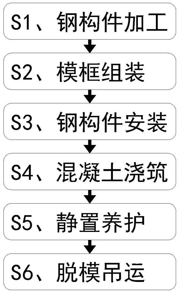
[0036] See attached Figure 1-10As shown, a method for manufacturing a steel-concrete structure assembled prefabricated wall, the manufacturing method specifically includes the following steps:

[0037] S1. Steel component processing: welding and processing the steel mesh components required for forming the prefabricated wall, and welding and processing the steel truss components required for forming the prefabricated wall with the assistance of the steel-concrete structure assembled prefabricated wall reinforcement truss welding auxiliary table;

[0038] S2. F...


PUM


Abstract

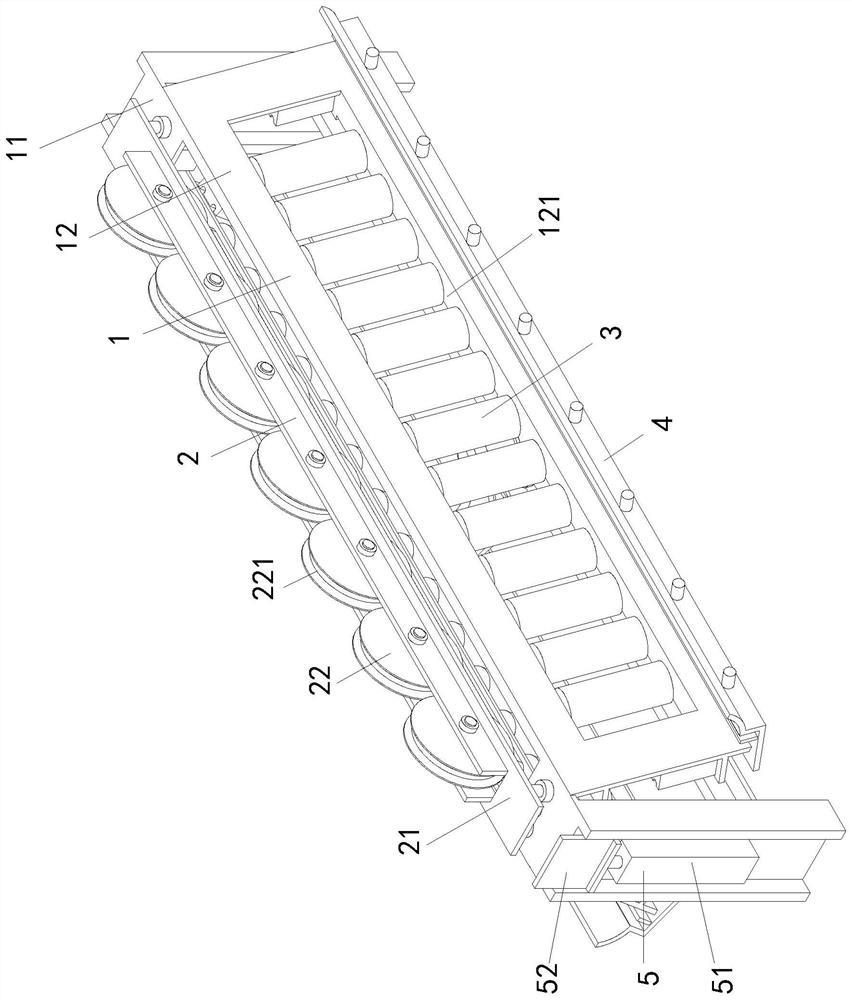
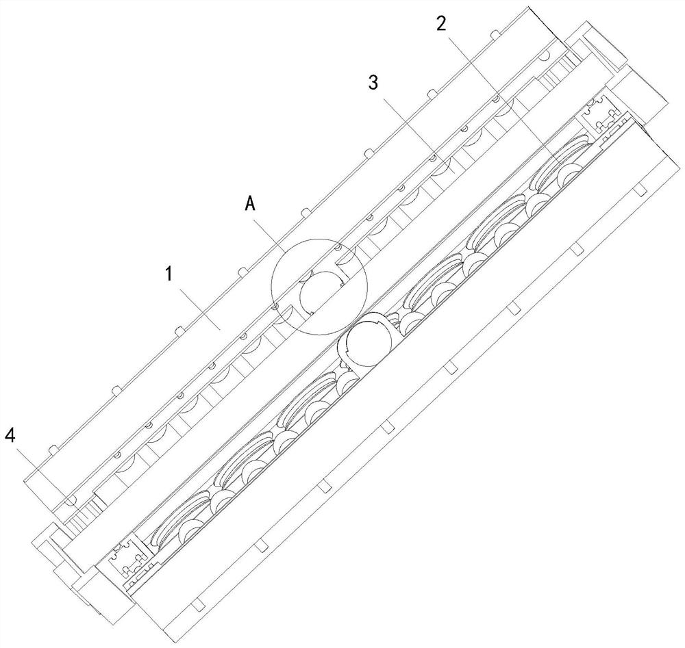
The invention relates to a manufacturing method of a steel-concrete structure assembly type prefabricated wall, in particular to a steel-concrete structure assembly type prefabricated wall steel bar truss welding auxiliary table which comprises a rack, an upper support positioning mechanism, an intermittent conveying mechanism, a lower support positioning mechanism and a front baffle positioning assembly. The upper support positioning mechanism comprises a lifting fine adjustment table arranged on a main support table and a row of upper support wheels distributed above the main support table;and the lower support positioning mechanism comprises two adjusting positioning air cylinders, a lower support plate, an auxiliary positioning plate and a lateral pressing assembly. The auxiliary table involved in the method provided by the invention can conduct rapid auxiliary positioning on a steel bar truss structure of the prefabricated wall, so that the problem that accurate lap joint formingis not easy in the actual welding process is solved, the effectiveness of lap joint contact of the steel bar truss structure is guaranteed, faulty soldered joints can be effectively prevented from being formed, the welding efficiency is improved, and meanwhile, the welding quality of the steel bar truss structure is ensured.

Description

technical field [0001] The invention relates to the technical field of building material production, and specifically proposes a method for manufacturing a steel-concrete structure assembled prefabricated wall. Background technique [0002] Prefabricated wall refers to a steel-concrete structure that can be assembled by laminating prefabricated panels and cast-in-place reinforced concrete layers. The prefabricated wall has good integrity, and the wall surface is flat, which is convenient for decoration of the facing layer. It is suitable for high-rise buildings and large-bay buildings that require high overall rigidity. In the prefabricated wall, steel members such as steel mesh and steel truss will be set to enhance the structural strength. The steel truss structure is mainly welded by broken line steel bars and straight steel bars. The specific structure is as attached Figure 10 As shown, the steel truss structure is composed of two broken-line steel bars welded in a tria...

Claims


Application Information

Patent Timeline
Patent Type & Authority Applications(China)
IPC IPC(8): B28B23/02B28B1/14B28B1/04B28B11/24B28B13/06B23K31/02
CPCB23K31/02B28B1/045B28B1/14B28B11/245B28B13/06B28B23/02
Inventor 吕振兴苏刚许旭
Owner 合肥集知网信息技术有限公司
Learn More