Drying device for textile printing and dyeing

A drying device, textile printing and dyeing technology, applied in textile and papermaking, textile material processing, textile material carrier processing, etc. Uniformity etc.

Inactive Publication Date: 2021-01-08
绍兴嘉越纺织机械有限公司
View PDF0 Cites 2 Cited by
  • Summary
  • Abstract
  • Description
  • Claims
  • Application Information

AI Technical Summary

Problems solved by technology

[0004] The object of the present invention is to provide a drying device for textile printing and dyeing to solve the problem that the drying device for textile printing and dyeing in the prior art in the above-mentioned background technology cannot increase the residence time of the cloth when the drying device for textile printing and dyeing in the prior art is used, resulting in the contact area between the cloth and the hot air Small, thus reducing the drying efficiency, and cannot divert the hot air, reducing the uniformity of contact between the hot air and the cloth, further reducing the drying efficiency and prolonging the working time

Method used


Image

  • Drying device for textile printing and dyeing
  • Drying device for textile printing and dyeing
  • Drying device for textile printing and dyeing

Examples


Embodiment 1

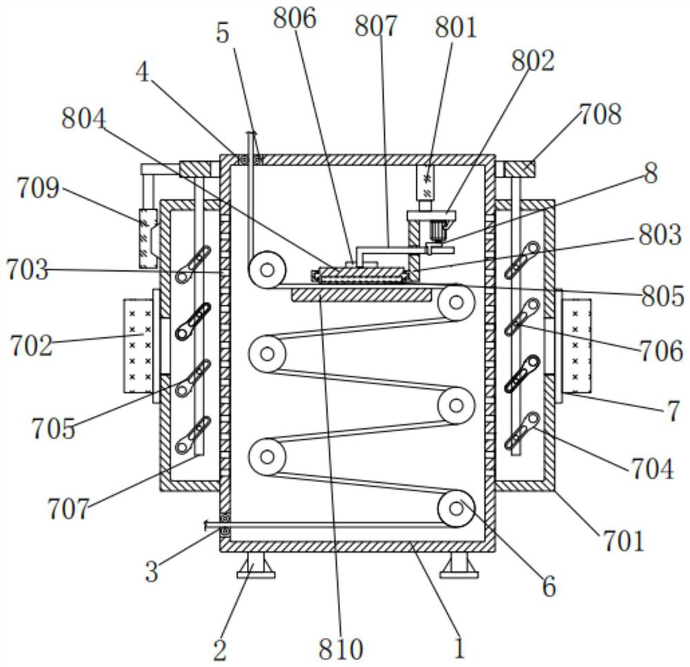
[0030] A drying device for textile printing and dyeing, comprising a box body 1, the bottom of the box body 1 is fixedly connected with a foot 2, a material inlet 3 is processed under the left end of the box body 1, and a material outlet is processed on the left side of the top of the box body 1 4. The inner walls of the feed port 3 and the discharge port 4 are rotatably connected with two round rods 5. The round rods 5 can prevent the cloth from being scratched and damaged. There are multiple round rollers 6 inside the box body 1. The round rollers 6 can be lifted The contact area between the cloth and the hot air, the round roller 6 is rotatably connected with the inner wall of the box body 1;

Embodiment 2

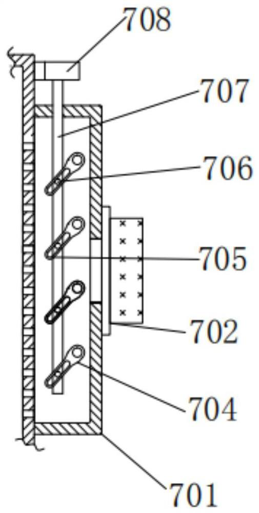
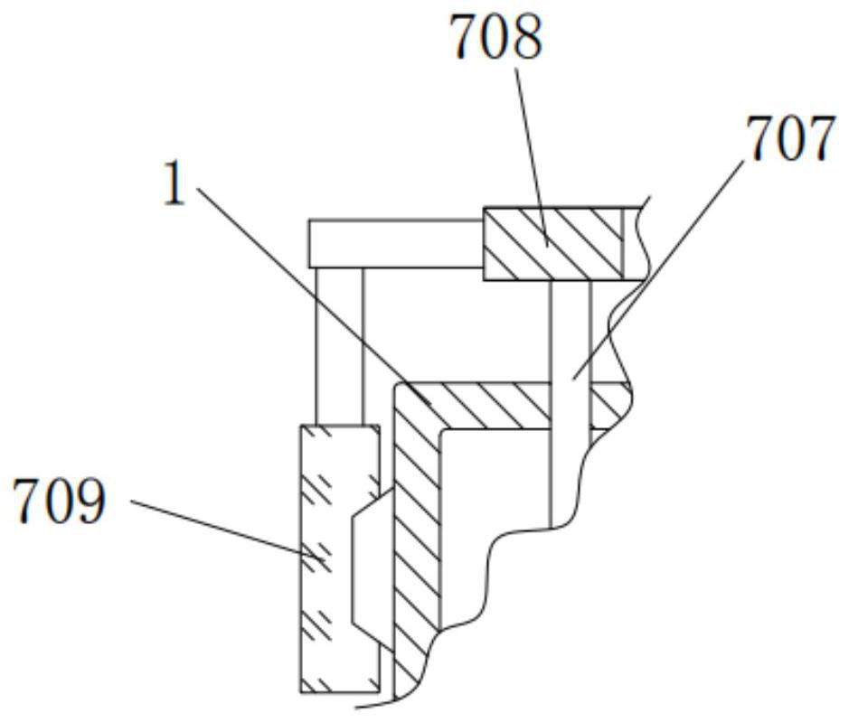
[0032] As an option, see Figure 1-3 , a drying device for textile printing and dyeing, the left and right sides of the cabinet 1 are provided with a drying assembly 7, and the drying assembly 7 includes a square cover 701, a hot air blower 702, a through hole 703, a dial 704, a round rod 705, and a through groove 706 , vertical bar 707, ring 708 and cylinder 709, the inner end of square cover 701 is fixedly connected with the left and right sides of box body 1, and the outside of square cover 701 is provided with hot air blower 702, and the model of hot air blower 702 is HAG-HP3A- 21. The air outlet end of the hot air blower 702 is connected with the outer end of the square cover 701, and the outer end of the inner end of the hot air blower 702 is fixedly connected with the outer end of the square cover 701. The inner side of the square cover 701 is provided with a through hole 703, and the through hole 703 The longitudinal range of the square cover 701 corresponds to the inn...

Embodiment 3

[0035] As an option, see figure 1 , 5And 6, the drying device for textile printing and dyeing, the inner top of the box body 1 is provided with a wrinkle removal assembly 8, and the wrinkle removal assembly 8 includes an electric push rod 801, a horizontal plate 802, a curved frame 803, a slide plate 804, an electric heating plate 805, and a clamping plate 806, the first curved rod 807, the second curved rod 808, the motor 809 and the bottom plate 810, the top of the electric push rod 801 is fixedly connected with the inner wall of the box body 1, the model of the electric push rod 801 is TG-700, and the electric push rod 801 A horizontal plate 802 is arranged below the telescopic end of the horizontal plate 802, and the top of the horizontal plate 802 is fixedly connected with the telescopic end of the electric push rod 801. The left end of the horizontal plate 802 is fixedly connected with a curved frame 803, and the left end of the curved frame 803 is equipped with a slide ...


PUM


Abstract

The invention discloses a drying device for textile printing and dyeing. The device comprises a box body, supporting legs are fixedly connected to the bottom of the box body, round rollers are rotatably connected with the inner wall of the box body, and drying assemblies are arranged at the left side and the right side of the box body. According to the drying device for textile printing and dyeing, through the arrangement of the multiple round rollers, when cloth is wound around the round rollers and walks at a low speed, the retention time of the cloth can be prolonged, the contact area of the cloth and hot air is greatly increased, and then the drying efficiency is improved; and through clearance fit of a through groove and a sliding rod and reverse arrangement of driving levers at the two sides, the driving levers at the two sides can swing reversely in a reciprocating manner at the same time when an air cylinder stretches out and draws back, so that the hot air is distributed, thecontact uniformity of the hot air and the cloth is improved, the drying efficiency is further improved, the working time is saved, and wrinkles of the cloth can be directly removed by arranging an electric heating plate and abutting against the cloth through a sliding plate and a bottom plate; and therefore, the cloth quality is improved, multiple purposes are achieved by one device, and the practicability is better.

Description

technical field [0001] The invention relates to the technical field of drying devices for textile printing and dyeing, in particular to a drying device for textile printing and dyeing. Background technique [0002] Printing and dyeing, also known as dyeing and finishing, is a processing method and a general term for pretreatment, dyeing, printing, finishing, washing, etc. It is often widely used in the textile industry, but drying treatment is often required after printing and dyeing. [0003] When the drying device for textile printing and dyeing in the prior art is in use, the residence time of the cloth cannot be increased, resulting in a small contact area between the cloth and the hot air, thereby reducing the drying efficiency, and it cannot divert the hot air, reducing the contact between the hot air and the cloth. The uniformity of contact will further reduce the drying efficiency and prolong the working time. At the same time, it is not possible to directly remove w...

Claims


Application Information

Patent Timeline
IPC IPC(8): D06B15/00D06B23/04D06C15/10
CPCD06B15/00D06B23/04D06C15/10
Inventor 俞淼轩
Owner 绍兴嘉越纺织机械有限公司
Why Eureka
Try Eureka