
Single-stage focusing spiral wave zone plate

A helical wave and zone plate technology, which is applied in the field of single-stage focusing helical zone plate, can solve the problems of limiting the production accuracy of the zone plate, energy loss through the zone plate, and image quality degradation, etc., so that the production accuracy is easy to control , improved monochrome performance, and highly flexible effects

Pending Publication Date: 2021-01-08
ZHENGZHOU UNIV
View PDF7 Cites 2 Cited by
  • Summary
  • Abstract
  • Description
  • Claims
  • Application Information

AI Technical Summary

Problems solved by technology

However, there is a problem that it is difficult to manufacture. In the past, people usually used the method of recording holograms and then exposing the recording medium to obtain Gabor zone plates, but this method is susceptible to problems such as the nonlinear response of the recording medium and the uncertainty of the point source. , and this method cannot produce Gabor zone plates suitable for short-wavelength bands (such as X-ray bands)
[0005] In 1992, Beynon and KirK et al. proposed an alternative method for making Gabor zone plates in the X-ray band (Gabor zone plate with binary transmittance values, Optics Letters, T.D.Beynon, I.Kirk and T.R.Mathews), which endows The characteristics of the binarized optical transfer function of the Gabor zone plate are improved, thus greatly reducing the difficulty of making the Gabor zone plate, but the Gabor zone plate designed by this method has a large number of sharp corners of different sizes, and the existence of a large number of sharp corners Directly limits the manufacturing accuracy of the zone plate
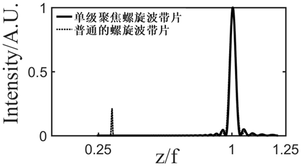
[0006] Traditional helical zone plates have multi-level focal points, which produce additional non-focus artifacts, resulting in a large loss of energy passing through the zone plate, resulting in a decrease in image quality
At the same time, the Gabor zone plate with only one pair of conjugate focal points is not ideal due to the nonlinear response of the recording medium and other uncertainties.

Method used


Image

  • Single-stage focusing spiral wave zone plate
  • Single-stage focusing spiral wave zone plate
  • Single-stage focusing spiral wave zone plate

Examples


Embodiment 1

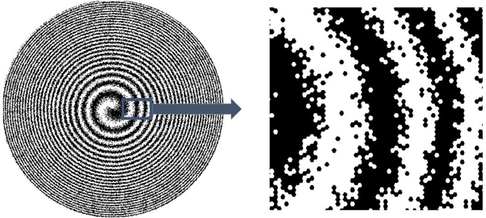
[0032] This embodiment discloses a single-stage focusing helical zone plate, refer to figure 1 and figure 2 As shown, it includes a silicon carbide transparent substrate and a plurality of tantalum (Ta) opaque elements formed on the silicon carbide transparent substrate.

[0033] In other embodiments, the material of the transparent substrate can also be ordinary glass or plexiglass light-transmitting material or one of silicon dioxide, silicon nitride and polyimide, and the opaque element can also be Chromium, gold (Au), aluminum, copper, nickel (Ni) or niobium, etc.

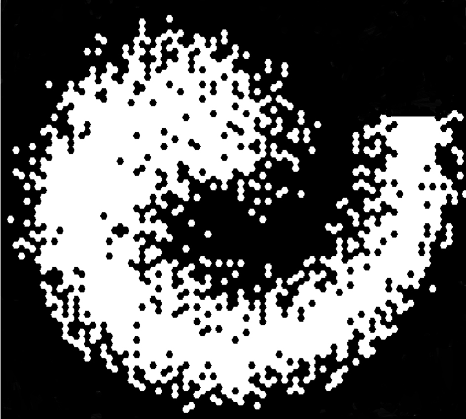
[0034] In this embodiment, the opaque primitives are regular hexagons with the same size, and may also be triangles, squares, or hexagons in other embodiments. like figure 1 Shown is the element distribution diagram of the first annular zone of the single-stage focusing helical zone plate of the present invention. If the regular hexagon filled with white is a light-transmitting element, the regular hexagon ...


PUM

PropertyMeasurementUnit
Thicknessaaaaaaaaaa

Abstract

The invention provides a single-stage focusing spiral wave zone plate. The wave zone plate comprises a transparent substrate and a plurality of lightproof elements formed on the transparent substrate;the number density of the lightproof elements is in cosine or sine distribution along the radial direction, i.e., the lightproof elements are distributed annularly and are randomly distributed alongrings; the transmittance function of the zone plate is described in the descriptions of the invention; in the transmittance function, l is a topological charge number, phi is an argument, n is the number of rings, ri is the radius of the nth ring, r1<2> is equal to lambda f, wherein lambda is the wavelength, and f is the focal length. The single-stage focusing spiral wave zone plate is only provided with a pair of conjugated first-stage focuses, so that interference and errors caused by high-stage diffraction can be eliminated, and vortex light beams can be generated; meanwhile, the structureof the single-stage focusing spiral wave zone plate only has a light-transmitting area and a light-proof area, since the single-stage focusing spiral wave zone plate is of a binary structure, and thesingle-stage focusing spiral wave zone plate is easy to manufacture. The characteristics of the single-stage focusing spiral wave zone plate show that the single-stage focusing spiral wave zone platecan be used as an optical conversion element for generating optical vortexes, edge enhanced imaging elements or X-ray bands.

Description

technical field [0001] The invention belongs to the technical field of zone plates, and in particular relates to a single-stage focusing spiral zone plate. Background technique [0002] In 1974, Nye and Berry first introduced the term singularity into the field of electromagnetic waves. In 1979, Berry, Nye and Wright successfully generated phase singularity in the laboratory by using multi-beam interference. In 1991, Brambilla et al. studied It was found that the beam carrying the phase singularity has a spiral phase, and then Coullet et al. found that there is a singularity in the laser cavity, and the mathematical expression of this spiral beam with a phase distribution is very similar to the vortex in the superfluid, for the first time Formally proposed the concept of "optical vortex". The light intensity of the vortex beam in the process of propagation is a ring structure, there is a phase singularity with uncertain phase and orbital angular momentum. This type of ligh...

Claims


Application Information

Patent Timeline
IPC IPC(8): G02B5/18
CPCG02B5/1876
Inventor 臧华平王晓霞王萌光苗壮磊
Owner ZHENGZHOU UNIV
Learn More