
Broadband large-inclination-angle low-sidelobe microstrip array antenna

A technology of microstrip array and large inclination angle, which is applied in the direction of antenna, resonant antenna, antenna array, etc., can solve the problems of high cost of TR components, large network loss, complex structure, etc., and achieve small thickness, large radiation impedance, and compact volume Effect

Active Publication Date: 2021-01-08
SHANGHAI RADIO EQUIP RES INST
View PDF3 Cites 1 Cited by
  • Summary
  • Abstract
  • Description
  • Claims
  • Application Information

AI Technical Summary

Problems solved by technology

[0003] In recent years, beam scanning antennas are mostly realized by mechanical and electronic methods. The mechanical beam scanning method requires a mechanical scanning device to realize the tilt angle of the main beam of the antenna, but the structure is too complicated, large in size, high in cost, and not easy to process. The array antenna can achieve multi-beam pointing by independently controlling the relative amplitude and phase of each radiating unit. This type of antenna has a fixed radiation aperture and is an ideal beam scanning antenna. However, the phased array antenna has a complex beamforming network and network loss. Large and expensive TR components

Method used


Image

  • Broadband large-inclination-angle low-sidelobe microstrip array antenna
  • Broadband large-inclination-angle low-sidelobe microstrip array antenna
  • Broadband large-inclination-angle low-sidelobe microstrip array antenna

Examples


Embodiment Construction

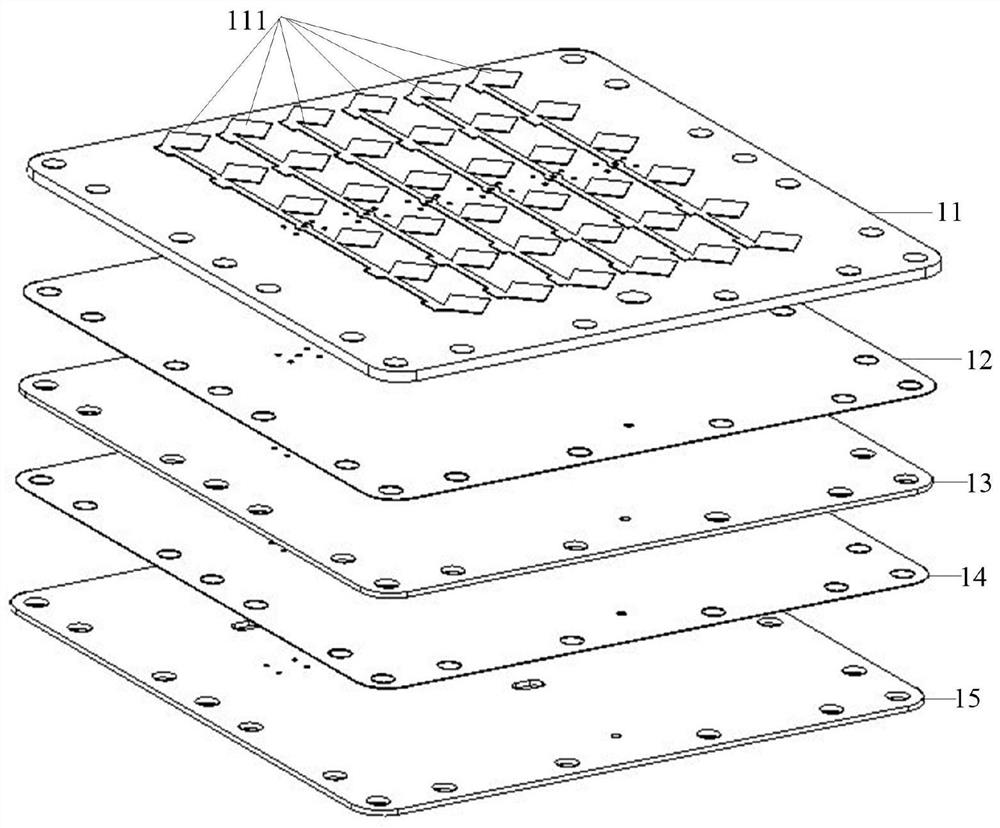
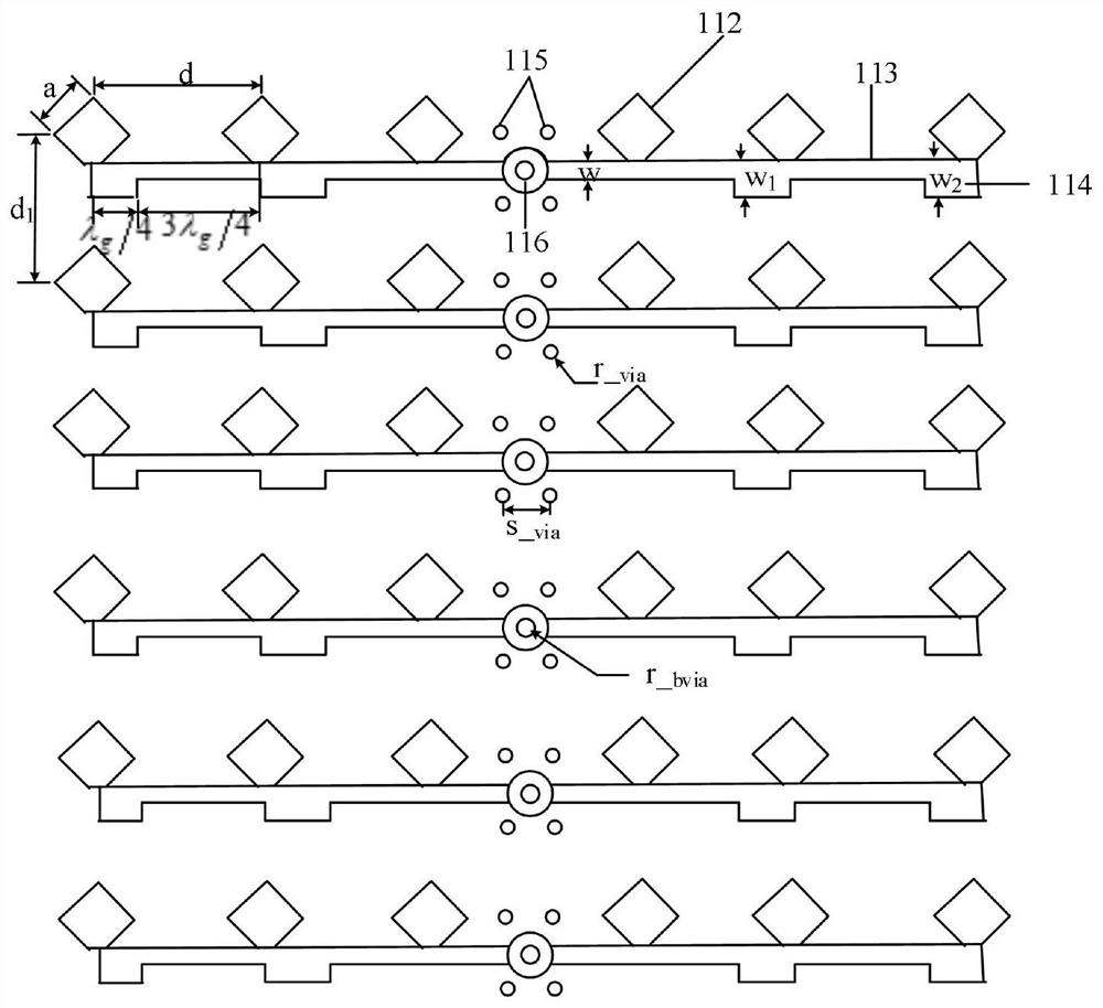
[0042] The following is attached figure 1 ~6 and the specific embodiment describe the present invention in further detail. The advantages and features of the present invention will become clearer from the following description. It should be noted that the drawings are in a very simplified form and all use imprecise scales, which are only used to facilitate and clearly assist the purpose of illustrating the embodiments of the present invention. In order to make the objects, features and advantages of the present invention more comprehensible, please refer to the accompanying drawings. It should be noted that the structures, proportions, sizes, etc. shown in the drawings attached to this specification are only used to match the content disclosed in the specification, for those who are familiar with this technology to understand and read, and are not used to limit the implementation of the present invention. condition, so it has no technical substantive meaning, and any modific...


PUM


Abstract

The invention discloses a broadband large-inclination-angle low-sidelobe microstrip array antenna. The antenna comprises a first dielectric substrate; a second prepreg; a third dielectric substrate; afourth prepreg; a fifth dielectric substrate; a first metal coating layer printed on the upper surface of the first dielectric substrate; a second metal coating layer printed on the lower surface ofthe first dielectric substrate; a third metal coating layer printed on the lower surface of a second dielectric substrate; and a fourth metal coating printed on the lower surface of a third dielectricsubstrate. Compared with a traditional microstrip array antenna, a series angle feed microstrip array is adopted, metalized through holes are adopted for feeding, and the antenna has the advantages of being wide in band, compact in size, small in thickness, low in cost and the like.

Description

technical field [0001] The invention relates to the field of antennas, in particular to a wide-band microstrip array antenna with large inclination angle and low sidelobe. Background technique [0002] Antennas are an important part of wireless mobile communication systems and radar systems. The rapid development of wireless communication and radar creates an urgent need for antennas with low sidelobes and specific beam inclinations. By controlling the tilt angle of the beam, the interference signal can be significantly suppressed and the system capacity can be improved. The series-fed microstrip antenna is an effective and economical method to realize the inclined beam. At the same time, the microstrip antenna also has the advantages of low profile, light weight, easy processing, low cost, and easy coplanar integration with microwave circuits. Therefore, the series-fed Compared with parallel-fed antenna array, microstrip antenna array has more compact structure and smalle...

Claims


Application Information

Patent Timeline
IPC IPC(8): H01Q1/50H01Q9/04H01Q1/36H01Q21/00
CPCH01Q1/50H01Q9/045H01Q1/36H01Q21/0006
Inventor 郭敏纪松花鹏程李政
Owner SHANGHAI RADIO EQUIP RES INST
Learn More