
Sliding bearing bush material and preparation method thereof

A technology for sliding bearings and bushings, which is applied in the field of electric arc and semi-solid composite additive manufacturing processes, can solve problems such as black oxide inclusions and pores, tin-based alloys are prone to spatter, and weld quality is more limited, so as to reduce tooling Effect of cost and machining allowance, improvement of welding efficiency and arc density, improvement of internal quality

Active Publication Date: 2021-01-15
JIANGSU UNIV OF SCI & TECH
View PDF4 Cites 2 Cited by
  • Summary
  • Abstract
  • Description
  • Claims
  • Application Information

AI Technical Summary

Problems solved by technology

However, in the arc additive manufacturing process, the arc temperature is as high as 2600K, and the tin-based alloy with a low melting point is prone to spatter and oxidation to form defects such as black oxide inclusions and pores, and the quality of welds in a protective atmosphere is more restricted by the surrounding environment; The easy flow of tin-based alloys has a great influence on the continuity of welding. In the actual welding process, the edge shape of the weld leg of the previous welding layer has an important impact on the quality of the next weld. Irregular weld legs are the cause of pores In order to ensure the formability of the welding layer and the quality of the weld seam, it is necessary to stop the welding process, conduct heat dissipation, and clean the surface of the welding layer according to the solidification completion of the welding bead, the generation of spatter and oxides, and limit the Therefore, when manufacturing bearing bushes used in large machinery, the thickness of the babbitt alloy layer is more than 100mm, the production cycle is long, and the cost of welding wire required in actual production is also relatively high

Method used


Image

  • Sliding bearing bush material and preparation method thereof
  • Sliding bearing bush material and preparation method thereof

Examples


Embodiment Construction

[0024] The present invention will be described in further detail below through specific examples, but the scope of the present invention will not be limited thereby.

[0025] Application: The bearing shell of the heavy-duty main shaft bearing for the rated power of 300MW hydroelectric generating set, the specification is φ1600mm×φ1400mm×1200mm.

[0026] Technical requirements: The steel back is made of No. 45 steel, and the total thickness of the Babbitt bonding layer and the friction-reducing layer is 100mm.

[0027] Preparation:

[0028] (1) Clean the No. 45 steel backing, degrease, derust, and dry.

[0029] (2) bonding layer deposition

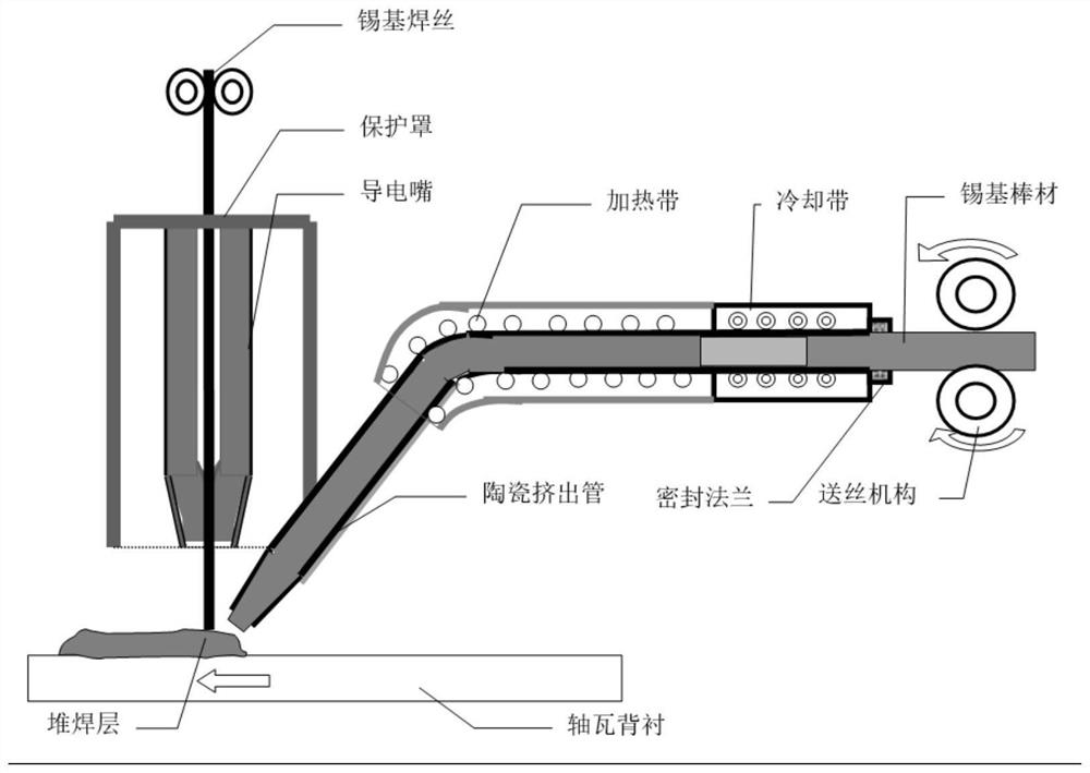
[0030] like figure 1 As shown, the angle between the welding torch of MIG welding and the extruded tube of semi-solid slurry ceramics is downward and the axis is 20-30° (that is, the angle between the extruded tube and the horizontal plane is 60-70°), and the current of the welding torch is set It is 200A, the voltage is 19V, the diamet...


PUM

PropertyMeasurementUnit
thicknessaaaaaaaaaa

Abstract

The invention discloses a sliding bearing bush material and a composite additive preparation process thereof. The bearing bush material is sequentially composed of a backing, a bonding layer and an anti-friction layer, the backing is made of medium-low carbon steel, the bonding layer and the anti-friction layer are both made of tin-based babbitt metal, and the bonding layer is made of tin-based babbitt metal with low Sb and Cu content. The bonding layer and the anti-friction layer are sequentially prepared by using a method of combining MIG welding and semi-solid extrusion. The specific preparation method comprises the steps that an MIG welding gun and a semi-solid slurry extrusion pipe keep a fixed angle, when the welding gun conducts MIG welding on the backing, the semi-solid extrusion pipe extrudes semi-solid materials to the same backing position at the same time, in this way, the bonding layer and the anti-friction layer are deposited on the surface of the backing in sequence, andtherefore the bearing bush material is prepared. The method is high in efficiency, the tool cost and the machining allowance can be greatly reduced, and good welding quality is achieved.

Description

technical field [0001] The invention belongs to the field of additive manufacturing, and in particular relates to an arc and semi-solid composite additive manufacturing process for preparing large-scale sliding bearing block materials. Background technique [0002] Tin-based Babbitt alloy is mainly used in bearing bushes, bearings, bushings and bushings of large mechanical spindles because of its superior comprehensive properties such as high anti-friction performance, good embedding, friction compliance and corrosion resistance. Among them, due to its large bearing capacity, shock absorption and wear resistance, it is an ideal bearing material for large machinery. [0003] Most of the Babbitt alloy bearings use medium and low carbon steel as the backing material (referred to as "steel backing"), through the hydrogen expansion annealing treatment, machining, cleaning, preheating, hot-dip tinning of the steel backing forgings, and using The method of gravity casting or centr...

Claims


Application Information

Patent Timeline
Patent Type & Authority Applications(China)
IPC IPC(8): B23K9/167B23K9/28B23K9/32
CPCB23K9/167B23K9/28B23K9/32
Inventor 张小立卢冶李小兵朱海洋
Owner JIANGSU UNIV OF SCI & TECH
Learn More