Sealing cover dismantling fixture and nuclear industrial waste barrel treatment device

A cover clamp and clamp technology, which is applied in the field of nuclear waste disposal equipment, can solve the problems of difficult maintenance of fully automatic cover unsealing equipment, lowering the efficiency of processing lines, and damage to operators, so as to reduce physical injuries of workers and production costs, and reduce The effect of adjusting the process multiple times and improving the processing speed

Inactive Publication Date: 2021-01-15
山东大学日照智能制造研究院
View PDF10 Cites 3 Cited by
  • Summary
  • Abstract
  • Description
  • Claims
  • Application Information

AI Technical Summary

Problems solved by technology

[0004] The inventor found that the maintenance of the current fully automatic cap opening equipment is relatively difficult and the maintenance cost is high, and although the semi-automatic processing line used more often can reduce part of the maintenance cost, it cannot achieve real unmanned operation without manual operation. Enter the curing workshop for close-range operation; on the one hand, radiation will cause unavoidable damage to the operator's body; The manual operation will reduce the efficiency of the entire processing line, and the current production and processing line is difficult to meet the actual demand for nuclear waste

Method used


Image

  • Sealing cover dismantling fixture and nuclear industrial waste barrel treatment device
  • Sealing cover dismantling fixture and nuclear industrial waste barrel treatment device
  • Sealing cover dismantling fixture and nuclear industrial waste barrel treatment device

Examples


Embodiment 1

[0044] In a typical implementation of the present disclosure, such as Figure 1-Figure 16 As shown, a cap removal jig is proposed.

[0045] Such as Figure 5 As shown, it mainly includes an installation disc 42, a positioning claw 43, a dismounting mechanism and a clamp 46. According to the principle of three-point circle fixing, at least three positioning claws, at least three dismounting mechanisms and at least three clamps are configured;

[0046] All positioning claws are arranged symmetrically around the center of the disk axis and are respectively rotatably matched with the disk. The positioning claws rotate relative to the disk to synchronously change the distance between the positioning claws and the disk axis, thereby changing the diameter of the circle defined by the positioning claws. The positioning claws can Contact and press the waste barrel, push the waste barrel to the coaxial position with the disc gradually, and gradually position the waste barrel to the posit...

Embodiment 2

[0073] In another typical implementation of the present disclosure, such as Figure 1-Figure 16 As shown, a nuclear industry waste barrel disposal device is proposed.

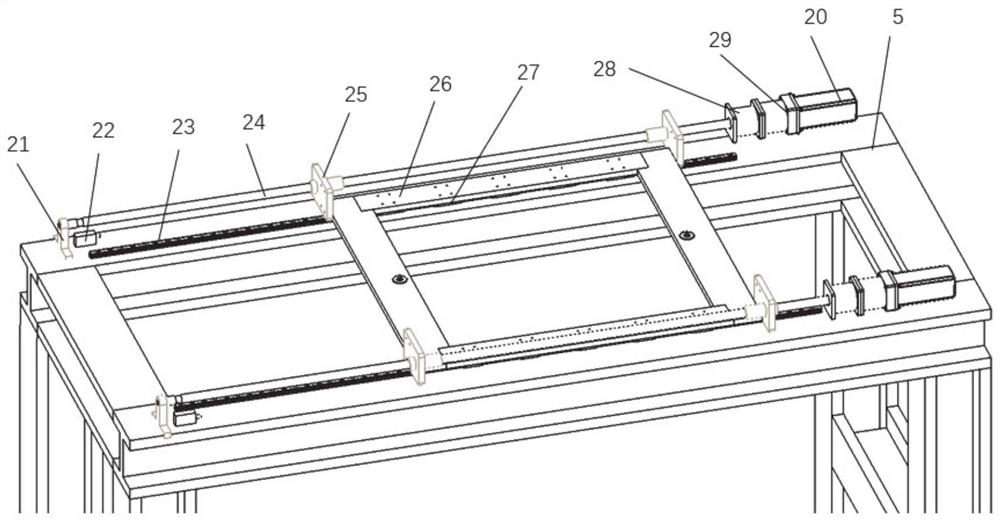
[0074] It mainly includes a three-axis mechanical arm, a conveying mechanism, a storage rack and the capping fixture described in Embodiment 1. The conveying mechanism includes a slide rail and a transport trolley arranged on the slide rail. The three-axis mechanical arm is erected on the slide rail through a supporting frame Above the rail, the end of the three-axis mechanical arm rotates to cooperate with the capping fixture, and the storage rack is arranged below the support frame and on one side of the slide rail;

[0075] A position drive mechanism is installed at the end of the three-axis mechanical arm, and the position drive mechanism cooperates with the cap removal jig through a corresponding transmission mechanism to drive the cap removal jig to rotate as a whole.

[0076] Specifically, for the three...

Embodiment 3

[0095] In yet another typical embodiment of the present disclosure, a working method of the nuclear industry waste barrel disposal device in Embodiment 2 is given.

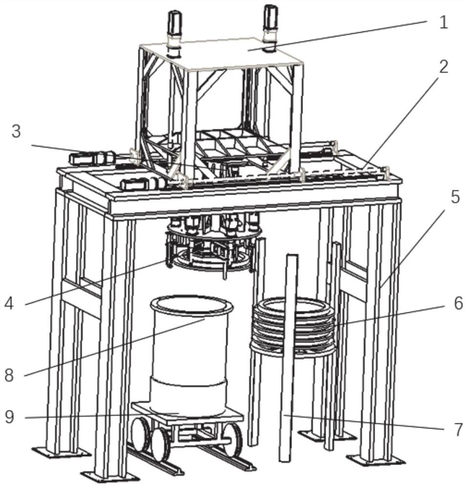
[0096] Such as figure 1 As shown, it is mainly composed of lifting mechanism 1, translation mechanism 2, rotation mechanism 3 and grasping mechanism 4. The above four mechanisms are installed on the support frame 5, and the removed metal bucket lid 6 is placed on one side On the bung storage frame 7 of the bung, the ladle body 8 is carried in and out by the transport dolly 9.

[0097] Its complete workflow is:

[0098] (1) Cap removal process

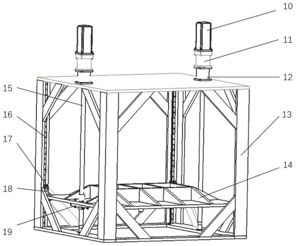
[0099] Such as figure 1 and figure 2 As shown, the transport trolley 9 transports the metal barrel with the cover to the designated position and stops, and the lifting mechanism 1 waiting above starts to move. Driven by the AC servo motor 10, the lifting mechanism 11 and the shaft coupling 12 lift The screw 15 rotates to drive the bearing plate 14 to descend. When the...


PUM


Abstract

The invention provides a sealing cover dismantling fixture and a nuclear industrial waste barrel treatment device, and relates to the field of nuclear waste treatment equipment. The fixture comprisesa disc, at least three locating claws, at least three dismounting and mounting mechanisms and at least three clamps, wherein the locating claws, the dismounting and mounting mechanisms and the clampsare mounted on the disc; all the locating claws are symmetrically arranged around the center of the axis of the disc and rotationally matched with the disc, and the locating claws rotate relative to the disc to synchronously change the distance between the locating claws and the axis of the disc; the dismounting and mounting mechanisms are arranged on the disc corresponding to the position of a connecting piece matched with a barrel cover, and a matching portion matched with the connecting piece is arranged at the tail end of each dismounting and mounting mechanism; and all the clamps are symmetrically arranged around the center of the axis of the disc and are hinged to the same telescopic mechanism through connecting rod mechanisms, and the telescopic mechanism stretches and contracts toenable the connecting rod mechanisms to drive the clamps to synchronously move in the radial direction of the disc. The special sealing cover dismantling fixture can be quickly located and accuratelyand reliably matched with a waste barrel, so that the effect of increasing the overall treatment speed is achieved, and the requirements of an existing machining production line are met.

Description

technical field [0001] The disclosure relates to the field of nuclear waste disposal equipment, in particular to a jig for removing and sealing a cap and a disposal device for nuclear waste barrels. Background technique [0002] The statements in this section merely provide background information related to the present disclosure and may not necessarily constitute prior art. [0003] The development and utilization of nuclear energy is in a stage of rapid development. At the same time, the proper disposal of nuclear waste has become an urgent problem to be solved on the road to nuclear power development. The cement curing line is an operation line for nuclear waste treatment, and the automatic cover opening device is the core component of the cement curing line. [0004] The inventor found that the maintenance of the current fully automatic cap opening equipment is relatively difficult and the maintenance cost is high, and although the semi-automatic processing line used mo...

Claims


Application Information

Patent Timeline
Patent Type & Authority Applications(China)
IPC IPC(8): B67B7/14B67B3/20
CPCB67B7/14B67B3/20
Inventor 姜兆亮李鑫德陈国鹏
Owner 山东大学日照智能制造研究院
Why Eureka
Try Eureka