Heating furnace flue gas waste heat recovery system and combustion system

A flue gas waste heat and recovery system technology, which is applied in the direction of combustion methods, lighting and heating equipment, furnaces, etc., can solve the problem that the latent heat of condensation of flue gas cannot be recovered, the low-temperature sensible heat and latent heat of condensation of flue gas are difficult to recover, and the flue gas of heating furnace can be reduced. In order to improve the comprehensive thermal efficiency, increase the content of water vapor and reduce the content of NOx, etc.

Active Publication Date: 2022-05-20
CHINA PETROLEUM & CHEM CORP +1
View PDF5 Cites 0 Cited by
  • Summary
  • Abstract
  • Description
  • Claims
  • Application Information

AI Technical Summary

Problems solved by technology

Due to the huge heat and low temperature, the conventional air heat exchange cannot recover the latent heat of condensation of this part of the flue gas
Therefore, the existing air heat exchange method is difficult to recover the low-temperature sensible heat and latent heat of condensation of the flue gas, which restricts the further improvement of the thermal efficiency of the heating furnace
[0004] At the same time, with the stringent national environmental protection regulations, the national standard stipulates the emission of heating furnaces, requiring that the NOx content in the flue gas of the process heating furnace should not exceed 100mg / m 3 , refining and chemical enterprises have successively carried out the transformation of low-nitrogen combustion technology, and the current emission has basically reached the national standard, but there are still certain technical difficulties in further reducing the NOx emission in the flue gas of the heating furnace

Method used


Image

  • Heating furnace flue gas waste heat recovery system and combustion system
  • Heating furnace flue gas waste heat recovery system and combustion system
  • Heating furnace flue gas waste heat recovery system and combustion system

Examples


Embodiment 1

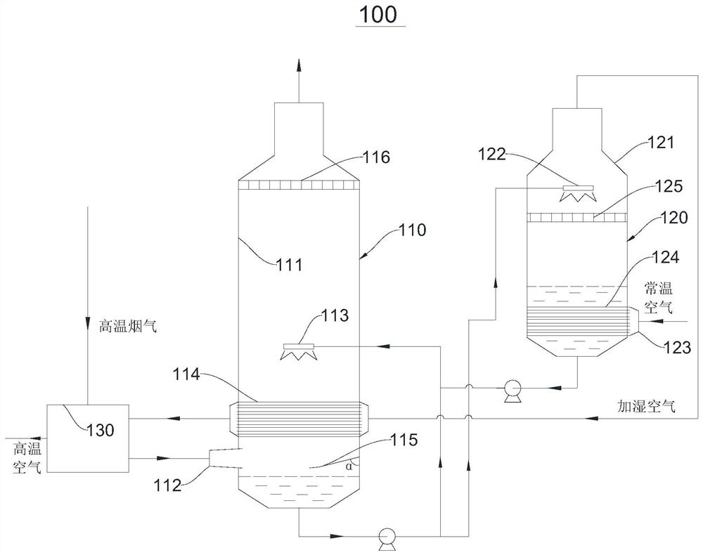
[0044] Please refer to figure 1 , this embodiment provides a heating furnace flue gas waste heat recovery system 100, which includes a spray cooling tower 110, which includes a cooling tower body 111, and a side of the cooling tower body 111 relatively close to the bottom of the tower is provided with a flue gas inlet 112 , and then the high-temperature flue gas formed in the heating furnace enters the spray cooling tower 110 through the flue gas inlet 112, and then realizes waste heat recovery of the flue gas.

[0045] It should be noted that the cooling tower body 111 is a conventional tower structure, the tower structure is set on the ground, the side relatively close to the ground is the bottom of the tower, and the side opposite to the bottom of the tower is the top of the tower.

[0046] The spray cooling tower 110 includes a first spray device 113 for spraying cooling liquid. The first spray device 113 is arranged in the cooling tower body 111 and is located on a side r...

Embodiment 2

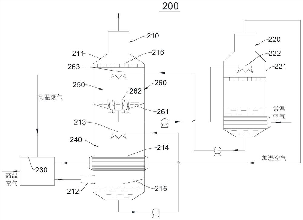
[0068] see image 3 , this embodiment provides a heating furnace flue gas waste heat recovery system 200, which includes a spray cooling tower 210, the spray cooling tower 210 includes a cooling tower body 211, the cooling tower body 211 is provided with a cooling section 240 and a condensation section 250, the cooling Section 240 communicates with condensation section 250, cooling section 240 is relatively close to the bottom of the tower, and condensation section 250 is relatively close to the bottom of the tower. At the same time, the side of the cooling tower body 211 relatively close to the bottom of the tower is provided with a flue gas inlet 212, that is, the flue gas inlet 212 is located at In the cooling section 240.

[0069]The spray cooling tower 210 includes a first spray device 213 and a spray heat exchanger 214, the first spray device 213 and the spray heat exchanger 214 are all located in the cooling section 240, and the first spray device 213 is arranged on the...

Embodiment 3

[0093] This embodiment also provides a process of recovering waste heat from flue gas using the waste heat recovery system of heating furnace flue gas in Embodiment 2. The temperature and the temperature of different liquids are different, as follows:

[0094] The temperature of the flue gas flowing out of the heating furnace is 280°C, and the temperature of the flue gas is reduced to 100°C after passing through the air preheater; the temperature of the air entering the air preheater is 70°C; the air entering the heating spray heat exchanger is 50°C ℃; the flue gas temperature after the heat exchange of the first spraying device is 65 ℃; the temperature of the cooling water sprayed by the first spraying device is 64 ℃; the temperature of the condensate sprayed by the third spraying device is 52 ℃; the third spraying The flue gas temperature after heat exchange of the device is 53°C.

[0095] The air entering the air humidification tower is 0°C; the temperature of the water ac...


PUM


Abstract

The invention relates to the field of recovery and treatment of flue gas from heating furnaces, in particular to a waste heat recovery system and combustion system of flue gas from heating furnaces. It includes a spray cooling tower and an air humidification tower. The spray cooling tower includes a cooling tower body and a first spray device for spraying cooling liquid. The side of the cooling tower body relatively close to the bottom of the tower is provided with a flue gas inlet. The shower device is set in the cooling tower body and is relatively close to the top of the tower, so that the flue gas and the cooling liquid form convection; the air humidification tower includes the air humidifier body and the second spray device for spraying liquid, and the air humidifier body is relatively close to the tower There is an air inlet on one side of the bottom, and the second spraying device is arranged in the air humidifier body and is relatively close to the top of the tower. The liquid outlet of the cooling tower body is connected to the second spraying device, so that the air and the liquid form convection, The air is heated and humidified. It can effectively recover and utilize the waste heat of the flue gas of the heating furnace while reducing the content of NOx in the flue gas.

Description

technical field [0001] The invention relates to the field of recovery and treatment of flue gas from heating furnaces, in particular to a waste heat recovery system and combustion system of flue gas from heating furnaces. Background technique [0002] The heating furnace is a large energy consumer and the main discharge outlet of refining and chemical enterprises. For refining and chemical enterprises, it is of great significance to improve the thermal efficiency of heating furnaces, reduce pollutant emissions, and save energy and reduce emissions. [0003] The existing technology generally adopts air preheating method to recover waste heat of flue gas, and improves energy utilization efficiency by reducing exhaust loss, but the current exhaust gas temperature of heating furnace is generally higher than 100°C. This is because if the flue gas temperature of the heating furnace is lower than 100°C, the conventional air preheater will suffer from low-temperature dew point corro...

Claims


Application Information

Patent Timeline
Patent Type & Authority Patents(China)
IPC IPC(8): F27D17/00F23L15/04
CPCF27D17/004F23L15/04Y02P10/25
Inventor 李玖重孙志钦张婧帆高晓红周天宇郜建松高跃成牛风宾段彦明
Owner CHINA PETROLEUM & CHEM CORP
Why Eureka
Try Eureka