
A kind of plasma module manufacturing method and plasma module

A plasma and production method technology, applied in separation methods, chemical instruments and methods, gas treatment, etc., can solve problems such as potential safety hazards and reduced treatment efficiency, and achieve the effect of eliminating "adhesion" area and increasing waste gas treatment efficiency

Active Publication Date: 2021-10-15
安徽朗澄环境科技有限公司
View PDF0 Cites 0 Cited by
  • Summary
  • Abstract
  • Description
  • Claims
  • Application Information

AI Technical Summary

Problems solved by technology

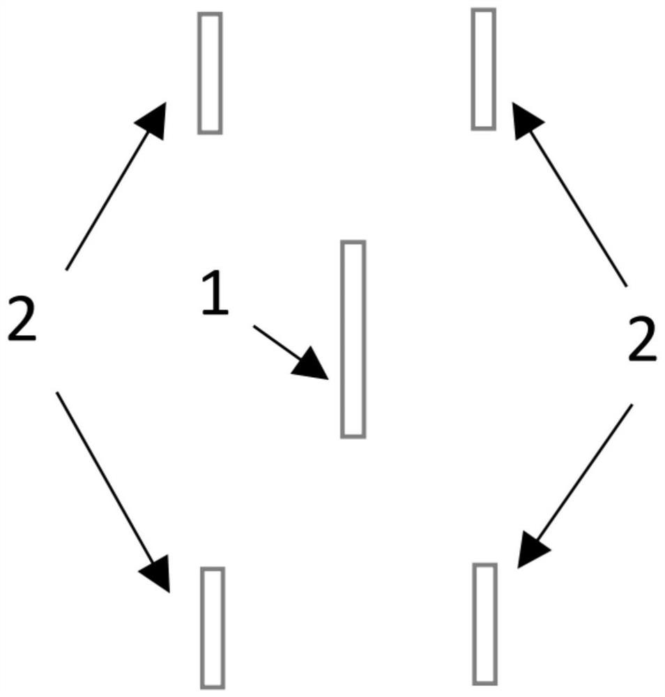
[0006] In view of the fact that the plasma module in the prior art is easy to absorb a large amount of pollutants, resulting in a decrease in treatment efficiency and even a potential safety hazard, the present invention provides a new method for making a plasma module, which uses three elements of "point, line, and surface" The structural design concept, through modal analysis, obtain the modal frequency and amplitude between the inner electrode and the outer electrode, determine the geometric size and material parameters of the inner electrode and the outer electrode; through the ion volume analysis, obtain the space electron of the inner electrode and the outer electrode Density distribution and spatial ion density distribution data are used to determine the spatial distance and spatial position of the inner electrode and the outer electrode, so that the "point" and "line" discharge of the inner electrode and the outer electrode sheet can generate "fan" plasma, reduce or The "adhesion" area of ​​pollutants in the plasma action area is basically eliminated, and the plasma phantom designed by this method has self-cleaning ability, which improves the efficiency of waste gas treatment

Method used


Image

  • A kind of plasma module manufacturing method and plasma module
  • A kind of plasma module manufacturing method and plasma module
  • A kind of plasma module manufacturing method and plasma module

Examples


Embodiment 1

[0048] like Image 6 As shown, this example provides a plasma module fabrication method, including the steps of:

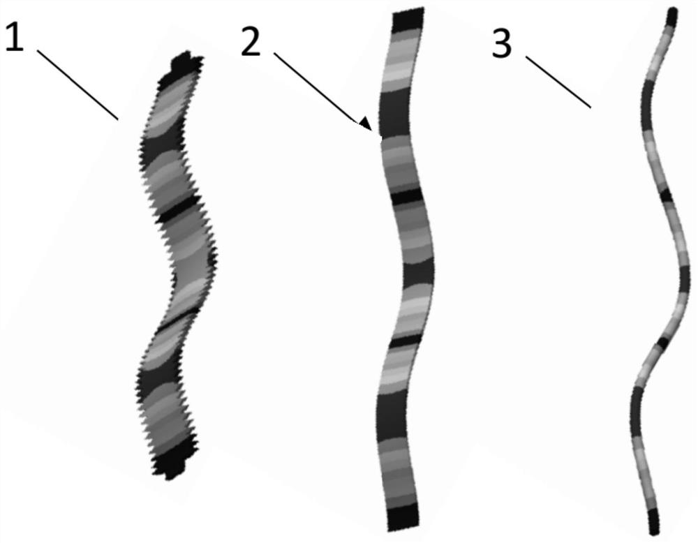
[0049] S100: Extract the internal electrode and the outer electrode model, perform modal analysis; the modal frequency and amplitude of the internal electrode and the outer electrode are obtained, and the geometric dimensions of the inner electrode and the outer electrode and the material parameters are determined.

[0050] Specifically, see Step S102-S110.

[0051] S102: From the design drawing, an internal electrode and an outer electrode model are extracted, and the inner electrode and the outer electrode model are introduced into the ANSYS software, and the inner electrode and the outer electrode model are networked.

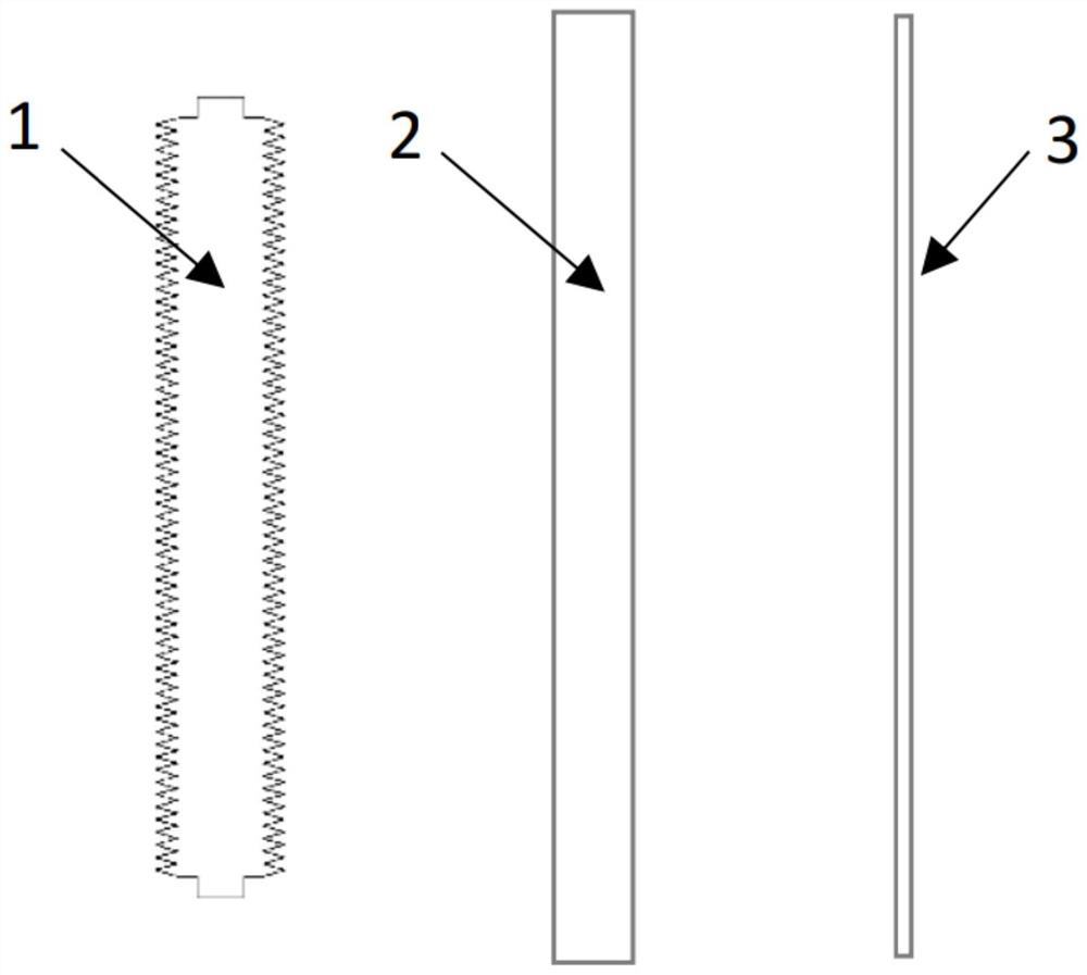
[0052] Specifically, the spatial size information of the internal electrode and the outer electrode is extracted from the design drawings, and the three-dimensional model is drawn. In this example, if figure 1 with 2 As shown, the extracted inner ele...

Embodiment 2

[0072] On the basis of the first embodiment, a plasma module is provided by the above-described plasma module fabrication method, wherein the plasma module includes an internal electrode sheet 1 and an outer electrode, an inner support frame 4. The outer support frame 5 and the insulator 6 are composed of one or both or both sides of the inner electrode sheet 1 having an equal distance arrangement, and is connected to the inner support frame 4; the outer electrode can be an external electrode sheet 2 Or one of the outer electrode rods 3; and the outer electrode is connected to the outer support frame, the inner support frame 4 and the outer support frame 5 connected by the insulator 6.


PUM


Abstract

The invention discloses a plasma module manufacturing method, which belongs to the technical field of environmental protection equipment manufacturing. This method adopts the structural design concept of "point, line, surface" and "three elements". Through modal analysis, the modal frequency and amplitude between the inner electrode and the outer electrode are obtained, and the geometric dimensions of the inner electrode and the outer electrode are determined. Parameters: Through ion volume analysis, the spatial electron density distribution and spatial ion density distribution data of the internal electrode and the external electrode are obtained, which are used to determine the spatial distance and spatial position of the internal electrode and the external electrode, so that the "point" of the internal electrode and the external electrode sheet , "line" discharge, generate "fan surface" plasma, reduce or basically eliminate the "adhesion" area of ​​pollutants in the plasma action area, the plasma phantom designed by this method has self-purification ability, and improves the efficiency of waste gas treatment . In addition, the present invention also provides a plasma module manufactured based on the above method.

Description

Technical field [0001] The present invention belongs to the technical field of environmental protection equipment, and more particularly to a method of fabricating a plasma module and a plasma module. Background technique [0002] The malodor / VOCS gas produced in the municipal sanitation and industrial production is not only caused serious pollution on the atmosphere, but also causing harm to the physical and mental health of the resident. The main source of contamination is the malodorous gas produced by municipal garbage and sewage, as well as the VOCS gas generated in industrial production, if these pollution gas is not treated, they will have a serious impact on the surrounding environment. Therefore, the effective gases of malodorous gas and VOCS gases have become one of the key issues that need to be solved in the process of my country's economic development. [0003] At present, my country's governance technology for malodor / VOCS gas is diversified, and various governa...

Claims


Application Information

Patent Timeline
Patent Type & Authority Patents(China)
IPC IPC(8): G06F30/23G06F30/17B01D53/32
CPCB01D53/323B01D2259/818G06F30/17G06F30/23
Inventor 徐从裕胡春明张华余红君王益俊
Owner 安徽朗澄环境科技有限公司
Learn More