Plant fiber filter element forming device of engine oil filter and using method thereof

A technology of oil filter and plant fiber, which is applied in the direction of textiles and papermaking, can solve the problems of poor oil passing capacity, cumbersome production process, and high physical exertion, and achieve the effects of improving efficiency, increasing corporate income, and increasing production capacity

Pending Publication Date: 2021-01-22
MINJIANG UNIV +1
View PDF0 Cites 0 Cited by
  • Summary
  • Abstract
  • Description
  • Claims
  • Application Information

AI Technical Summary

Problems solved by technology

Most of the oil filters currently on the market rely on a single paper filter element to intercept and filter out harmful impurities in the oil. The smaller the pores of the filter paper, the better the filtering effect, but the worse the oil passing ability. In the process, steps such as stacking paper are required, and the production process is relatively cumbersome. In order to solve this problem and improve the service life of the filter element, some new oil filter elements are currently made of plant fibers, and filter cotton is arranged in the filter body in sequence according to the oil flow direction. and plant fiber, the porosity of the far-infrared ceramic filter core is 80%-90%, and the pore density is 30-50ppi. Engine oil can improve the fluidity of engine oil, reduce the wear speed of the engine, thereby reducing the energy consumption of the engine, and has a huge application prospect, but in the process of making and molding the plant fiber, it is all manual, and the efficiency is low and the physical exertion is large.

Method used


Image

  • Plant fiber filter element forming device of engine oil filter and using method thereof
  • Plant fiber filter element forming device of engine oil filter and using method thereof
  • Plant fiber filter element forming device of engine oil filter and using method thereof

Examples


Embodiment Construction

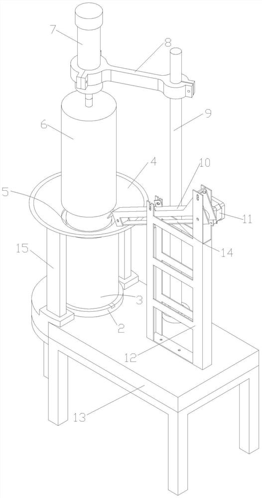
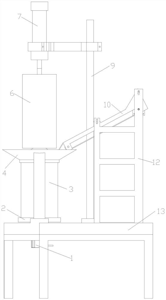
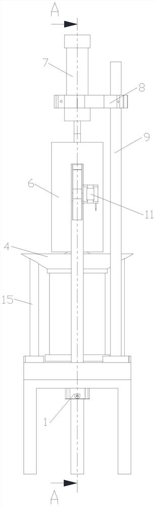
[0023] The present invention will be further described below in conjunction with the accompanying drawings.

[0024] see Figure 1 to Figure 5 , the present invention provides a plant fiber filter element forming device for an oil filter, including a workbench 13, a rotating base 2 is installed on the left part of the workbench 13, an outer cylinder 3 is installed on the rotating base 2, and the An inner cylinder 5 is mounted on the rotating base 2 inside the outer cylinder 3, a support base 12 is installed on the right part of the workbench 13, and a conveyor belt 14 is installed on the support base 12, and the conveyor belt 14 is close to the outer cylinder One end of 3 is docked with the outer cylinder 3, and a support rod 9 is installed on the workbench 13 placed on the conveyor belt, and a connecting block 8 is fixed on the support rod 9, and a connecting block 8 is installed on the connecting block 8. Telescopic cylinder 7, the lower end of the push rod of the telescopi...


PUM


Abstract

The invention relates to a plant fiber filter element forming device of an engine oil filter and a using method thereof. The device comprises a workbench, a rotary base is installed on the left portion of the workbench, an outer cylinder is installed on the rotary base, an inner cylinder is installed on the portion, located in the outer cylinder, of the rotary base, and a supporting base is installed on the right portion of the workbench. A conveying belt is installed on the supporting base, the end, close to the outer barrel, of the conveying belt is in butt joint with the outer barrel, a supporting rod is installed on the workbench, a connecting block is fixed to the supporting rod, a telescopic air cylinder is installed on the connecting block, and a pressing barrel is fixed to the lower end of a push rod of the telescopic air cylinder. An annular space formed between the inner barrel and the outer barrel is located under the cross section of the side edge of the pressing barrel. Automatic extrusion forming of the plant fiber material is achieved, manpower is saved, compared with manual production, the production efficiency is greatly improved, the capacity can be increased, andthe enterprise income is increased.

Description

technical field [0001] The invention relates to the technical field of filter production equipment, in particular to a plant fiber filter element forming device for an oil filter and a method for using the same. Background technique [0002] Oil filter, also known as oil grid. It is used to remove impurities such as dust, metal particles, carbon deposits and soot particles in the oil to protect the engine. During the working process of the engine, metal wear debris, dust, carbon deposits and colloidal deposits oxidized at high temperatures, water, etc. are continuously mixed into the lubricating oil. The function of the oil filter is to filter out these mechanical impurities and colloids to keep the lubricating oil clean and extend its service life. The oil filter should have strong filtering ability, small flow resistance and long service life. Generally, several filters with different filtration capacities are installed in the lubrication system - filter, coarse filter ...

Claims


Application Information

Patent Timeline
IPC IPC(8): D21J3/00
CPCD21J3/00
Inventor 唐晓腾吴金总涂家福林向春朱益斌肖宏宇吴杨宁郑祥盘郭益深成楚楚董春兰叶红英
Owner MINJIANG UNIV
Why Eureka
Try Eureka