
Mooring unmanned aerial vehicle

An unmanned aerial vehicle and tethering technology, applied in the field of unmanned aerial vehicles, can solve the problems of heavy metal cables, limit the flying height of unmanned aerial vehicles, and high cost of high-power and high-voltage control devices, so as to enhance the load capacity and improve the tethering. Endurance time and the effect of increasing flight altitude

Inactive Publication Date: 2021-01-26
JILIN UNIV
View PDF9 Cites 0 Cited by
  • Summary
  • Abstract
  • Description
  • Claims
  • Application Information

AI Technical Summary

Problems solved by technology

The current tethered drone still uses metal cables as the power supply method for the drone. Due to the heavy weight of the metal cable, the flying height of the drone is greatly limited, and in order to reduce the weight of the cable, the weight of the cable has to be reduced. diameter, so that the current that the cable can transmit is very small, so high-voltage power transmission has to be used, that is, the 220V voltage is boosted to high voltage on the ground, and after reaching the drone, the high-voltage power supply system has two modes of operation, one way Yes: the transmission voltage can directly match the high-voltage motor, and the voltage does not need to be converted to directly drive the motor. The advantage is that the structure is relatively simple. The disadvantage is that the high-voltage motor needs to be designed, and the cost of high-power high-voltage control devices is relatively high; another way is: Design a switching power supply for step-down on the UAV platform to drive the low-voltage motor on the existing UAV, but the switching power supply is also restricted by the power-to-weight ratio and the size of high-power high-voltage control devices

Method used


Image

  • Mooring unmanned aerial vehicle

Examples


Embodiment Construction

[0018] The following will clearly and completely describe the technical solutions in the embodiments of the present invention with reference to the accompanying drawings in the embodiments of the present invention. Obviously, the described embodiments are only some, not all, embodiments of the present invention. Based on the embodiments of the present invention, all other embodiments obtained by persons of ordinary skill in the art without making creative efforts belong to the protection scope of the present invention.

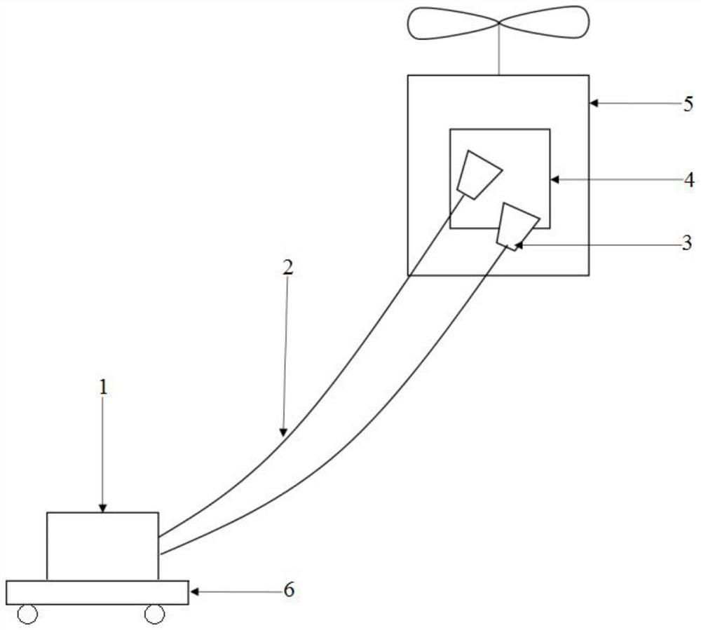
[0019] The purpose of the present invention is to provide a tethered unmanned aerial vehicle to solve the problems existing in the prior art, reduce the energy consumption of the unmanned aerial vehicle, enhance the loading capacity of the unmanned aerial vehicle, increase the flight height, and significantly increase the endurance time of the unmanned aerial vehicle.

[0020] In order to make the above objects, features and advantages of the present invention ...


PUM


Abstract

The invention discloses a mooring unmanned aerial vehicle and relates to the technical field of unmanned aerial vehicles. The mooring unmanned aerial vehicle comprises a laser, an optical fiber, a laser beam expander, a solar cell and an unmanned aerial vehicle body, wherein the laser is used for being arranged on the ground, and the solar cell and the laser beam expander are both arranged on theunmanned aerial vehicle body; the other end of the optical fiber is connected with an input end of the laser beam expander, the output end of the laser beam expander faces the solar cell, and an output end of the solar cell is electrically connected with the unmanned aerial vehicle body. According to the mooring unmanned aerial vehicle, energy consumption of the unmanned aerial vehicle is reduced,the loading capacity of the unmanned aerial vehicle is enhanced, the flight height is increased, and the endurance time of the unmanned aerial vehicle is remarkably prolonged.

Description

technical field [0001] The invention relates to the technical field of unmanned aerial vehicles, in particular to a tethered unmanned aerial vehicle. Background technique [0002] At present, drones have been widely used in various civil and military occasions, and drones that can fly or stay in the air for a long time have their special needs, such as tethered drones used as emergency communications. Due to the limited battery capacity of the drone, and the weight of the battery itself can be compared with the weight of the drone itself, the working time of the drone is further shortened. The current tethered drone still uses metal cables as the power supply method for the drone. Due to the heavy weight of the metal cable, the flying height of the drone is greatly limited, and in order to reduce the weight of the cable, the weight of the cable has to be reduced. diameter, so that the current that the cable can transmit is very small, so high-voltage power transmission has ...

Claims


Application Information

Patent Timeline
Patent Type & Authority Applications(China)
IPC IPC(8): H04B10/2575B64F3/02
CPCB64F3/02H04B10/2575
Inventor 赵毅卢明鑫刘畅秦后运刘一鸣魏松彭翀
Owner JILIN UNIV
Learn More