Device for efficiently removing SO3 in flue gas after wet desulphurization

A wet desulfurization and flue gas technology, applied in the field of flue gas treatment, can solve the problems of high investment and operation costs, complex technical system, unstable removal efficiency, etc., to reduce investment costs and operating costs, enhance removal effect, The effect of increased contact chance

Pending Publication Date: 2021-01-29
ZHEJIANG FUCHUNJIANG ENVIRONMENTAL THERMOELECTRIC CO LTD
View PDF0 Cites 0 Cited by
  • Summary
  • Abstract
  • Description
  • Claims
  • Application Information

AI Technical Summary

Problems solved by technology

At present, flue gas generally adopts a combined method to realize SO 3 removal, such as low and low temperature dust removal, wet desulfurization, wet electrostatic and other whole-process flue gas collab

Method used


Image

  • Device for efficiently removing SO3 in flue gas after wet desulphurization
  • Device for efficiently removing SO3 in flue gas after wet desulphurization

Examples


Embodiment 1

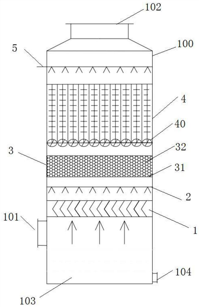
[0057] Embodiment 1, a method for SO in flue gas after wet desulfurization 3 High-efficiency removal device, as an independent reactor:

[0058] Including the cylindrical tower body 100, since the cylindrical tower body 100 has a bottom surface, the bottom inner cavity of the cylindrical tower body 100 is used as a liquid collection pool 103, and is arranged on the side wall of the cylindrical tower body 100 corresponding to the liquid collection pool 103 There is a liquid outlet 104; a flue gas inlet 101 is arranged on the side wall near the bottom of the cylindrical tower body 100, and the flue gas inlet 101 is located above the liquid collection tank 103 (that is, above the liquid outlet 104); the flue gas inlet 101 is inclined downward by 5-10°.

[0059] A flue gas outlet 102 is provided on the top of the cylindrical tower body 100 , so the flue gas inlet 101 and the flue gas outlet 102 are both connected to the inner cavity of the cylindrical tower body 100 .

[0060] A...


PUM

PropertyMeasurementUnit
Diameteraaaaaaaaaa
Heightaaaaaaaaaa
Concentrationaaaaaaaaaa

Abstract

The invention discloses a device for efficiently removing SO3 in flue gas after wet desulphurization. The device comprises a cylindrical tower body; a flue gas inlet is formed in the bottom of the cylindrical tower body or the side wall, close to the bottom, of the cylindrical tower body; a flue gas outlet is formed in the top of the cylindrical tower body; an inertia demister, an agglomeration agent ejector, a filler demister, a cyclone electrostatic device and a flusher are sequentially arranged in an inner cavity of the cylindrical tower body from bottom to top; the inertia demister is located above the flue gas inlet; the flusher is located below the flue gas outlet. The device provided by the invention realizes refined and efficient removal of SO3 particles with different sizes and SO3 in different phase states through ordered optimized combination of inertial collision, particle aggregation, filler absorption and filtration, centrifugal demisting and electrostatic demisting.

Description

technical field [0001] The invention relates to the field of flue gas treatment, in particular to a kind of SO2 after wet desulfurization 3 purification device. Background technique [0002] SO during combustion 3 The formation mechanism of the coal mainly includes the following parts: During the high-temperature combustion process in the boiler, the sulfur in the coal is oxidized, and a small part (about 0.5% to 1.5%) is oxidized into SO 3 ; SCR denitrification reactors are generally installed at the tail of coal-fired boilers to reduce NO x Emissions, V in the catalyst installed in the SCR deNOx reactor 2 o 5 Components that catalyze SO in flue gas 2 , and partially oxidized to SO 3 . Usually for coal-fired units without denitrification devices, SO 3 The generation rate accounts for 1% of the total sulfur content; for units installed with SCR denitrification devices, SO 3 The formation rate is higher, usually can account for 1.5-2% of the total sulfur content. SO...

Claims


Application Information

Patent Timeline
IPC IPC(8): B01D50/00B03C1/30
CPCB01D50/00B03C1/30
Inventor 徐少娟叶明华余咨文章丹吴祖良
Owner ZHEJIANG FUCHUNJIANG ENVIRONMENTAL THERMOELECTRIC CO LTD
Why Eureka
Try Eureka