
Ash removal device and steelmaking production line

An ash cleaning device and ash cleaning technology, which are applied in the directions of manufacturing converters, separation of dispersed particles, and improvement of process efficiency, can solve the problems of poor flue gas purification effect, etc. effect of work

Pending Publication Date: 2021-01-29
BEIJING JINGCHENGKELIN ENVIRONMENTAL PROTECTION TECH +1
View PDF0 Cites 1 Cited by
  • Summary
  • Abstract
  • Description
  • Claims
  • Application Information

AI Technical Summary

Problems solved by technology

[0005] For the problem of poor purification effect of converter flue gas in the high temperature range (650°C to 800°C) in related technologies, no effective solution has been given so far

Method used


Image

  • Ash removal device and steelmaking production line
  • Ash removal device and steelmaking production line
  • Ash removal device and steelmaking production line

Examples


Embodiment approach 1

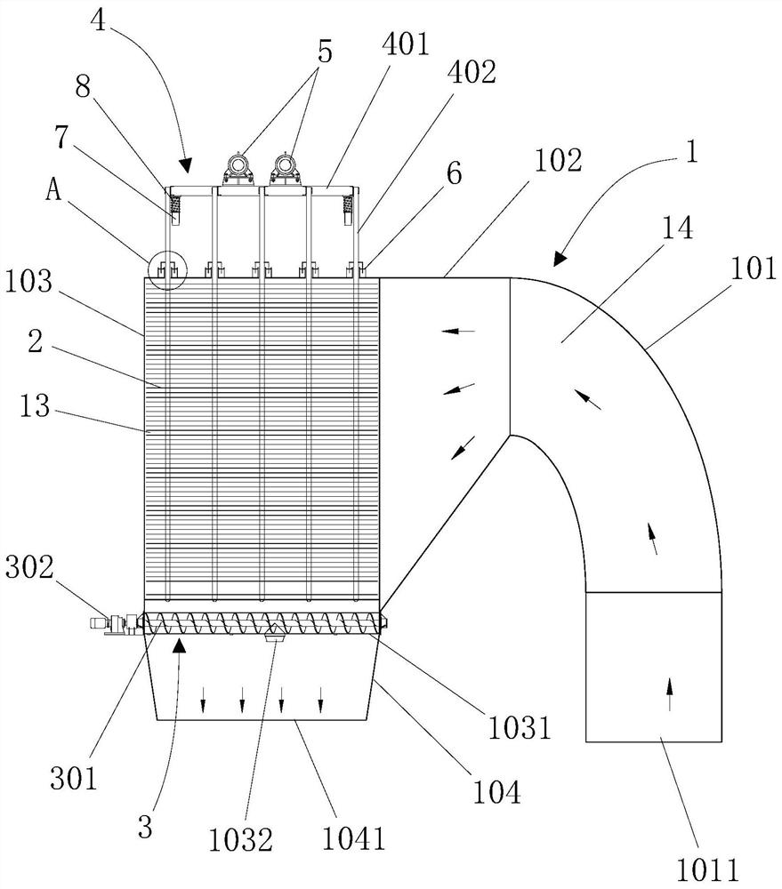
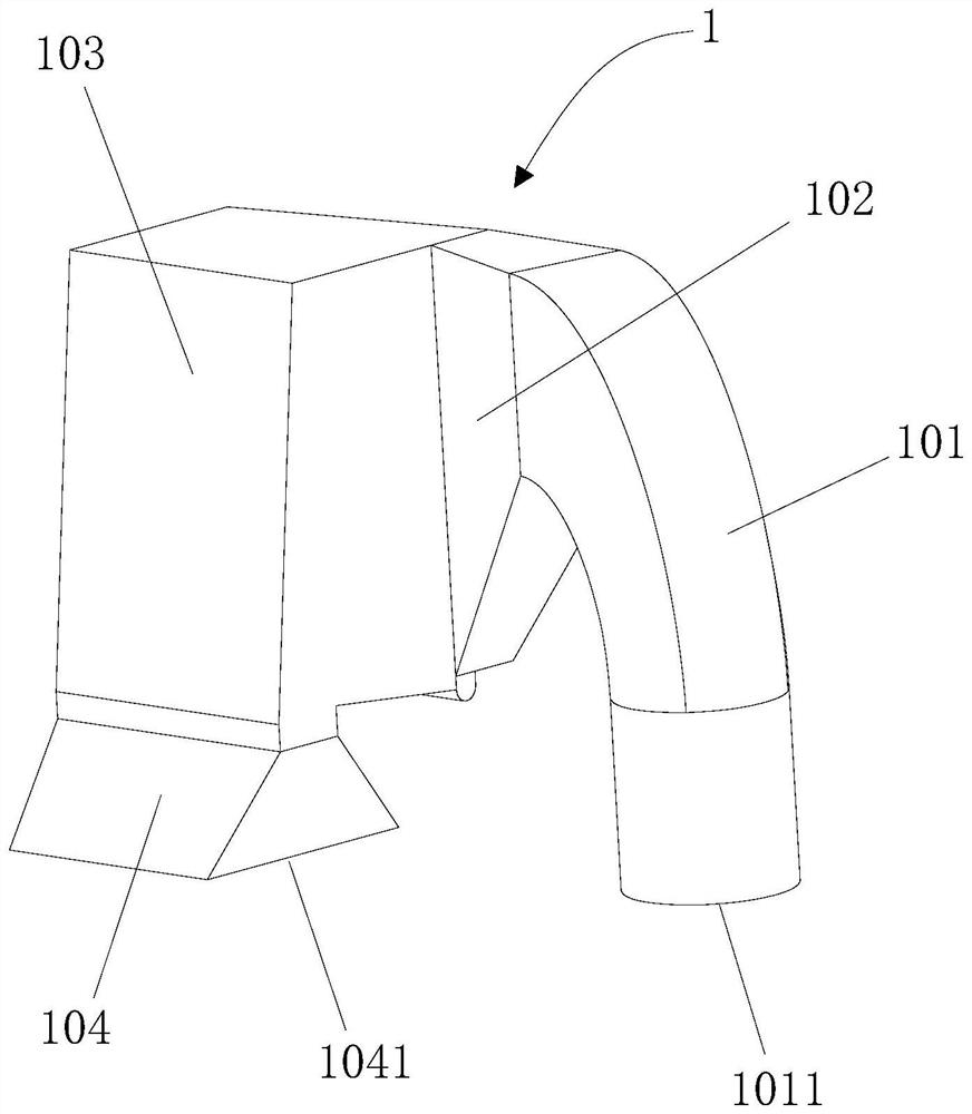
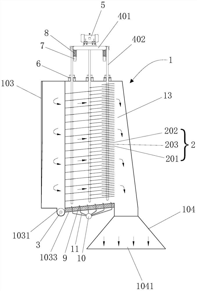
[0063] Such as Figure 1 to Figure 6 As shown, the present invention provides a kind of ash removal device, and this ash removal device comprises housing 1 and a plurality of ash falling boards 2, and each ash falling board 2 is used for carrying out dust (soot or ash) in high temperature flue gas Collecting, wherein: the shell 1 is respectively provided with a flue gas input port 1011 and a flue gas output port 1041, the flue gas input port 1011 is used to connect with the converter steelmaking cooling flue, and the flue gas output port 1041 is used to connect with the high temperature flue gas The recovery equipment is connected, and the housing 1 is formed with a storage chamber 13 for accommodating the ash plates 2 and a flue gas conveying channel 14 capable of transporting high-temperature flue gas. The side end faces are connected, the other end of the flue gas delivery channel 14 is connected to the flue gas input port 1011, and the flue gas output port 1041 is located ...

Embodiment approach 2

[0093] The invention provides a steelmaking production line. The steelmaking production line includes a converter, high-temperature flue gas recovery equipment and the above-mentioned ash removal device. The converter is provided with a converter steelmaking cooling flue, and the high-temperature flue gas outlet of the converter passes through the The cooling flue is connected to the flue gas input port 1011 of the dust removal device, and the flue gas output port 1041 of the dust removal device is connected to the high temperature flue gas recovery equipment.

[0094] The characteristics and advantages of the steelmaking production line of the present invention are:

[0095]The steelmaking production line can smoothly collect the dust in the high-temperature flue gas produced by the converter, achieve the purpose of separating the solid dust in the high-temperature flue gas, and ensure the full purification of the high-temperature flue gas, and the separated The ash slag can ...


PUM


Abstract

The invention discloses an ash removal device and a steelmaking production line. The ash removal device comprises a shell and a plurality of ash falling plates for collecting dust in high-temperatureflue gas, wherein the shell is provided with a flue gas input port and a flue gas output port; a containing cavity for containing the ash falling plates and a flue gas conveying channel for conveyingthe high-temperature flue gas are formed in the shell; the two ends of the flue gas conveying channel communicate with the end face of one side of the containing cavity and the flue gas input port correspondingly; the flue gas output port is located below the shell and communicates with the bottom of the containing cavity; the ash falling plates are arranged in the containing cavity in a layered manner from top to bottom, a gap is reserved between every two adjacent ash falling plates, and therefore a flat flue gas runner is formed between every two adjacent ash falling plates; and each ash falling plate is provided with a plurality of ash leaking holes. The ash removal device and the steelmaking production line solve the technical problem that the purification effect of converter flue gasin a high-temperature interval is poor.

Description

technical field [0001] The present invention relates to the field of steelmaking equipment, and further relates to a soot cleaning device and a steelmaking production line, in particular to an intermittent soot cleaning device for cleaning and dedusting a steelmaking flue in an airtight space and steel production lines. Background technique [0002] Converter oxygen blowing steelmaking is the main form of steelmaking in steel mills at present. Its main feature is intermittent periodic operation. Generally, the production cycle of each furnace of steel is 40 minutes, and the cycle operation is repeated. Among them, a large amount of gas and dust (containing a large amount of FeO, Fe 2 o 3 and CaO and other active and exothermic alkaline dust), slag and heat, etc., the temperature of these high-temperature flue gases containing dust can drop to about 800°C after passing through the movable fume hood, fixed fume hood and vaporization cooling flue. It can be transported to su...

Claims


Application Information

Patent Timeline
Patent Type & Authority Applications(China)
IPC IPC(8): C21C5/40B01D45/02B01D45/18
CPCC21C5/40B01D45/02B01D45/18Y02P10/20
Inventor 杨源满井小海杨明华万庆明
Owner BEIJING JINGCHENGKELIN ENVIRONMENTAL PROTECTION TECH
Learn More