Light source equipment

A light source and equipment technology, applied in the direction of electric light source, mechanical equipment, lighting and heating equipment, etc., can solve the problems of inability to maintain the polarization state of circularly polarized light, difficulty in original polarization state of incident light, low luminous efficiency of light source equipment, etc., to achieve work The effect of long life, small etendue, and high color rendering index

Pending Publication Date: 2021-01-29
赫尔曼友瀚范贝赫库姆 +1
View PDF5 Cites 2 Cited by
  • Summary
  • Abstract
  • Description
  • Claims
  • Application Information

AI Technical Summary

Problems solved by technology

[0004] figure 1 The scheme shown is designed based on the assumption that the blue light of circularly polarized light is reflected by the reflective layer 50a of the wavelength conversion device 50 and its polarization state remains unchanged (that is, it is still circularly polarized light). However, according to common sense of optics, we know that the polarization After light is diffusely reflected, it is difficult for the reflected light to fully retain the polarization state of the original incident light. Usually, the reflected light may partially retain the polarization state of the original incident light or completely become unpolarized light.
while in figure 1 In the solution shown, the reflect

Method used


Image

  • Light source equipment
  • Light source equipment
  • Light source equipment

Examples


Example Embodiment

[0078] Example 1

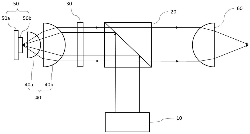
[0079] like Figure 7 As shown, a light source device disclosed in this embodiment includes a light source 701, a light guiding optical system 702, a reflective element 703, a polarizing beam splitter 704, a collecting optical system, a wavelength conversion device 706, and a light concentrating optical system. The polarization beam splitter 704 is a cubic polarization beam splitter, and the transmission area of ​​the reflective element 703 is a light through hole 703a. The light guiding optical system 702 is composed of a positive lens 702a and a positive lens 702b, and the positive lens 702b is located at the light aperture 703a of the reflective element 703 . The collection optical system is composed of a lens group 705 including a lens 705a and a lens 705b. The wavelength converting device 706 includes a reflective layer 706a and a wavelength converting layer 706b disposed on the reflective layer 706a. The condensing optical system is constituted by a...

Example Embodiment

[0081] Example 2

[0082] like Figure 8As shown, a light source device disclosed in this embodiment includes a light source 801, a light guide optical system 802 (consisting of a positive lens 802a and a positive lens 802b), a reflective element 803 (the transmission area is a light hole 803a), and a polarizing beam splitter 804 , a collecting optical system (consisting of a lens group 805 including a lens 805a and a lens 805b), a wavelength conversion device 806, a light collecting optical system (consisting of a focusing lens 807) and a quarter-wave plate 808.

[0083] The difference between this embodiment and Embodiment 1 is that a quarter-wave plate 808 is provided between the polarization beam splitter 804 and the lens group 805 . The blue light of the S polarized light emitted by the light source 801 is guided by the positive lens 802 a and the positive lens 802 b to the polarization beam splitter 804 , and then is reflected by the polarization beam splitter 804 and t...

Example Embodiment

[0084] Example 3

[0085] like Figure 9 As shown, a light source device disclosed in this embodiment includes a light source 901, a light guiding optical system 902 (composed of a positive lens 902a and a positive lens 902b), a reflective element 903, a polarizing beam splitter 904, and a collection optical system (composed of a lens 905a and a positive lens 902b). Lens group 905 of lens 905b), wavelength conversion device 906 (including reflective layer 906a and wavelength conversion layer 906b disposed on reflective layer 906a), light-condensing optical system (composed of a focusing lens 907), quarter-wave Sheet 908 and uniform light optical system.

[0086] The difference between this embodiment and Embodiment 2 lies in the addition of a uniform light optical system. The uniform light optical system is composed of a diffuser 909, and the diffuser 909 is located at the light hole 903a of the reflective element 903 for uniform blue light emitted by the light source 901, t...


PUM


Abstract

The invention provides light source equipment. The equipment is characterized by comprising a light source, a reflection element, a polarization beam splitter and a wavelength conversion device, a transmission area of the reflection element allows light of a first wave band emitted by the light source to pass through or enter the polarization beam splitter after passing through, and a reflection area of the reflection element can reflect the light of the first wave band from the polarization beam splitter, so the light is emitted back to polarizing beam splitter, the light can be reused, and the light emitting efficiency of the light source equipment is improved. The light source equipment provided by the invention has the characteristics of high brightness, small optical expansion amount,high color rendering index, long service life and the like, and can be applied to systems requiring high illumination intensity and small optical expansion amount, such as an entertainment illumination system, a projection system, an automobile illumination system, a medical illumination system, a searchlighting illumination system, a field operation illumination system, a navigation illuminationsystem, a portable illumination system and the like.

Description

technical field [0001] The invention belongs to the field of lighting, in particular to the field of solid-state light source lighting. The light source device provided by the present invention can be applied to systems that require high light intensity and small etendue, such as entertainment lighting systems, projection systems, automotive lighting systems, medical lighting systems, search lighting systems, field operation lighting systems, Nautical lighting systems, portable lighting systems, etc. Background technique [0002] As an ideal point light source, laser has the advantages of small etendue, long life and no mercury. Using it as a light source to excite the fluorescent body can produce colored light or white light, and at the same time cooperate with the use of optical elements to obtain an ideal light-emitting device with a small etendue. [0003] figure 1 It is a structural schematic diagram of an existing polarization-splitting light source device. like f...

Claims


Application Information

Patent Timeline
IPC IPC(8): F21S2/00F21V7/04F21V9/00F21V9/30F21V5/00F21V7/00F21V7/06F21V8/00G03B21/20G02B27/28
CPCF21S2/00F21V7/04F21V9/00F21V9/30F21V5/002F21V7/00F21V7/06G03B21/204G03B21/2066G03B21/2073G03B21/208G02B27/283G02B27/286F21V2200/00
Inventor 赫尔曼·友瀚·范·贝赫库姆郑华
Owner 赫尔曼友瀚范贝赫库姆
Why Eureka
Try Eureka