Light source device

A light source device and light source technology, applied in electric light sources, projection devices, lighting devices, etc., can solve the problems that the polarization state of circularly polarized light cannot be maintained, reflected light is difficult, and cannot be emitted.

Active Publication Date: 2021-01-29
赫尔曼友瀚范贝赫库姆 +1
View PDF4 Cites 1 Cited by
  • Summary
  • Abstract
  • Description
  • Claims
  • Application Information

AI Technical Summary

Problems solved by technology

However, according to common sense of optics, we know that after polarized light is diffusely reflected, it is difficult for the reflected light to fully retain the polarization state of the original incident light. Usually, the reflected light may partially retain the polarization state of the original incident light or completely become unpolarized light.
while in figure 1 In the scheme shown, the reflection of circularly polarized blue light by the reflective diffuser 70 is diffuse reflection, because only in this way can a uniform white light output be obtained, but a considerable part of it will be reflected by the reflective diffuser 70 The final blue light cannot maintain the polarization state of circularly polarized light, and even all the blue light reflected by the reflective diffuser 70 will become unpolarized light, which will cause at least part of the blue light to be unable to pass through the quarter-wave plate 50 Afterwards, it becomes the blue light of S polarized light, so that it cannot be completely emitted from the light source device, which will lead to low luminous efficiency of the entire light source device

Method used


Image

  • Light source device
  • Light source device
  • Light source device

Examples


Embodiment 1

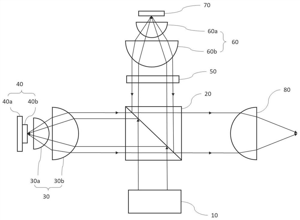
[0090] Such as Figure 12 As shown, a light source device disclosed in this embodiment includes a light source 1201, a light guiding optical system 1202, a reflective element 1203, a polarization beam splitter 1204, a first collecting optical system, a wavelength conversion device 1206, a second collecting optical system, and a scattering optical system. system and concentrating optical system. Polarizing beam splitter 1204 is a cube type polarizing beam splitter. The transmissive area of ​​the reflective element 1203 is a light hole 1203a. The light guiding optical system 1202 is composed of a positive lens 1202a and a positive lens 1202b, and the positive lens 1202b is located at the light passing hole 1203a of the reflective element 1203 . The first collection optical system is composed of a lens group 1205 including a lens 1205a and a lens 1205b. The wavelength converting device 1206 includes a reflective layer 1206a and a wavelength converting layer 1206b disposed on t...

Embodiment 2

[0093] Such as Figure 13 As shown, the light source device disclosed in this embodiment includes a light source 1301, a light guide optical system 1302 (consisting of a positive lens 1302a and a positive lens 1302b), a reflective element 1303 (the transmission area is a light hole 1303a), a polarizing beam splitter 1304, a first A collecting optical system (consisting of lens group 1305 including lens 1305a and lens 1305b), wavelength converting device 1306 (comprising reflective layer 1306a and wavelength converting layer 1306b disposed on reflecting layer 1306a), second collecting optical system (comprising The lens group 1307 of lens 1307a and lens 1307b), the scattering optical system (consisting of a reflective scattering plate 1308), the converging optical system (consisting of a focusing lens 1309) and the quarter wave plate 1310.

[0094] The difference between this embodiment and Embodiment 1 is that a quarter-wave plate 1310 is provided between the polarization beam...

Embodiment 3

[0096] Such as Figure 14As shown, a light source device disclosed in this embodiment includes a light source 1401, a light guiding optical system 1402 (consisting of a positive lens 1402a and a positive lens 1402b), a reflective element 1403, a polarizing beam splitter 1404, a first collecting optical system (comprising a lens 1405a and a lens group 1405 of lens 1405b), wavelength conversion device 1406 (comprising reflective layer 1406a and wavelength conversion layer 1406b disposed on reflective layer 1406a), second collection optical system (composed of lens group comprising lens 1407a and lens 1407b 1407), a scattering optical system (consisting of a reflective scattering plate 1408), a concentrating optical system (consisting of a focusing lens 1409), a quarter wave plate 1410 and a homogenizing optical system.

[0097] The difference between this embodiment and Embodiment 2 is that the uniform light optical system is added, wherein the uniform light optical system is co...


PUM


Abstract

The invention provides a light source device, which is characterized by comprising a light source, a reflection element, a polarization beam splitter, a wavelength conversion device and a scattering optical system. A transmission region of the reflection element allows light of a first wave band emitted by the light source to pass through or be transmitted through and then enter the polarization beam splitter, and a reflection region can reflect the light of the first wave band from the polarization beam splitter, so that the light is emitted back to the polarization beam splitter, the light can be reused, and the light emitting efficiency of the light source device is improved. The light source device has the advantages of being high in brightness, small in optical expansion amount, highin color rendering index, long in service life and the like, and can be suitable for systems needing high illumination intensity and small optical expansion amount, such as an entertainment illumination system, a projection system, an automobile illumination system, a medical illumination system, a searchlighting illumination system, a field operation illumination system, a navigation illuminationsystem, and a portable illumination system.

Description

technical field [0001] The invention belongs to the field of lighting, in particular to the field of solid-state light source lighting. The light source device provided by the present invention can be applied to systems that require high light intensity and small etendue, such as entertainment lighting systems, projection systems, automotive lighting systems, medical lighting systems, search lighting systems, field operation lighting systems, Nautical lighting systems, portable lighting systems, etc. Background technique [0002] As an ideal point light source, laser has the advantages of small etendue, long life and no mercury. Using it as a light source to excite the fluorescent body can produce colored light or white light, and at the same time cooperate with the use of optical elements to obtain an ideal light-emitting device with a small etendue. [0003] figure 1 It is a structural schematic diagram of an existing polarization-splitting light source device. Such as...

Claims


Application Information

Patent Timeline
Patent Type & Authority Applications(China)
IPC IPC(8): F21S2/00F21V7/04F21V9/00F21V9/30F21V5/00F21V7/00F21V7/06F21V8/00G03B21/20G02B27/28
CPCF21S2/00F21V7/04F21V9/00F21V9/30F21V5/002F21V7/00F21V7/06G03B21/204G03B21/2066G03B21/2073G03B21/208G02B27/283G02B27/286F21V2200/00Y02A90/10
Inventor 赫尔曼·友瀚·范·贝赫库姆郑华
Owner 赫尔曼友瀚范贝赫库姆
Why Eureka
Try Eureka