Clamping rod extrusion test device and use method

A technique of clamping rods and blocks, applied in measuring devices, using stable tension/pressure to test the strength of materials, and using stable torsion to test the strength of materials, etc. , inability to test and other problems, to achieve the effect of improving the efficiency of factory pressure inspection and low production cost

Pending Publication Date: 2021-01-29
山东国晶新材料有限公司
View PDF13 Cites 0 Cited by
  • Summary
  • Abstract
  • Description
  • Claims
  • Application Information

AI Technical Summary

Problems solved by technology

This device is not suitable for small clamping rods, it is difficult to fix, and the clamping rod is made of boron nitride, which is fragile and can easily cause damage during the fixing process, so it cannot be tested
[0005] In view of this, it is necessary to design a device that can perform pressure testing on rectangular clamping rods, which can effectively improve the efficiency of factory pressure testing, prevent unqualified parts from entering the market, and affect the use of subsequent helical traveling wave tubes.

Method used


Image

  • Clamping rod extrusion test device and use method
  • Clamping rod extrusion test device and use method

Examples


Embodiment 1

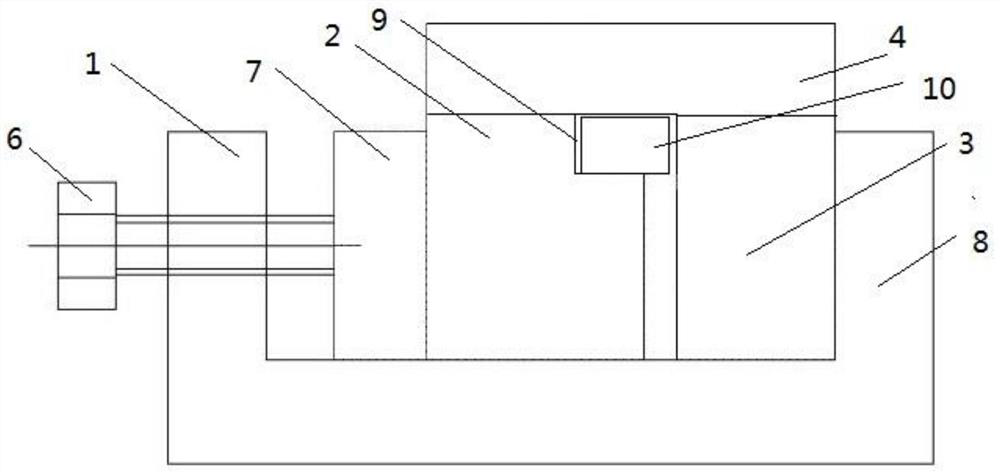
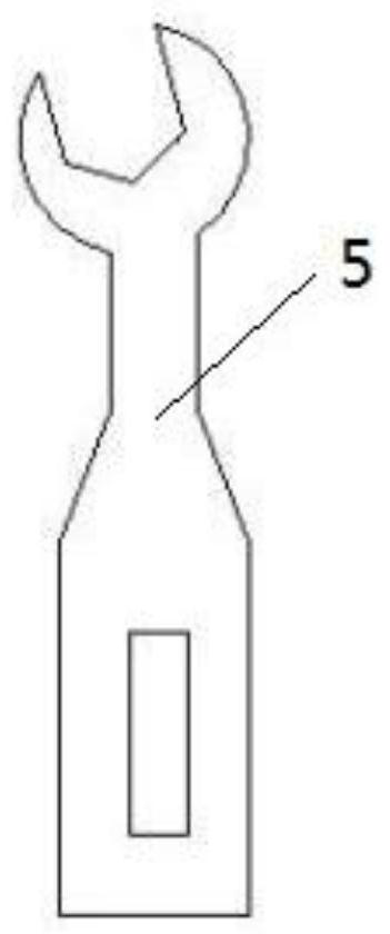
[0029] Such as Figure 1-2 As shown, this embodiment provides a device for clamping rod extrusion testing, including an operation table 1, a clamp block A2, a clamp block B3 and a torque wrench 5. The operation table 1 includes a vise, and the connection between the screw of the vise and the handle is Set as a nut 6, the nut 6 is connected to the torque wrench 5, the clamp block A2 is set on the inside of the movable clamp body 7 of the vise, the clamp block B3 is set on the inside of the fixed clamp body 8 of the vise, and the clamping rod 10 is set on the clamp block A2 and Between clamping block B3.

[0030] A cuboid groove 9 is arranged at the upper end of one side of the clamping block A2 clamping the clamping rod 10, and the clamping rod 10 is arranged in the groove 9, and the clamping rod 10 is clamped by the groove 9 and the clamping block B3 to ensure that the clamping rod 10 Does not flip horizontally after being squeezed.

[0031] The width of the bottom surface o...

Embodiment 2

[0039] A device for clamping rod extrusion test, the structure is as described in embodiment 1, the difference is that the extrusion direction of the clamping rod 10 is consistent with the direction of the layer structure of the clamping rod 10, and the fragility of the clamping rod Test the direction of the layer structure to ensure that the minimum bearing pressure of the clamping rod meets the standard.

Embodiment 3

[0041] A device for clamping rod extrusion test, the structure is as described in embodiment 1, the difference is that clamp block A2, clamp block B3 and clamp block C4 are all cuboids, clamp block A, clamp block B and clamp block C They are all made of die steel, which is not easily deformed, and the processing parallelism is 0.02mm, which ensures that the force on the clamping rod is even and avoids affecting the test results.


PUM


Abstract

The invention relates to a clamping rod extrusion test device and a use method, and belongs to the technical field of helix traveling-wave tubes. The device comprises an operation table, a clamping block A, a clamping block B and a torque wrench, the operation table comprises a bench clamp, a nut is arranged at the joint of a bench clamp lead screw and a handle and connected with the torque wrench, the clamping block A is arranged on the inner side of a movable clamp body of the bench clamp, the clamping block B is arranged on the inner side of a fixed clamp body of the bench clamp, and a clamping rod is arranged between the clamping block A and clamping block B. According to the invention, the pressure test requirement of the clamping rod is met, the delivery pressure test efficiency of the clamping rod is effectively improved, and unqualified parts are prevented from flowing into the market to influence the subsequent use of the helix traveling-wave tube.

Description

technical field [0001] The invention relates to a clamping rod extrusion testing device and a using method, which belong to the technical field of helical traveling wave tubes. Background technique [0002] The helical traveling wave tube plays an indispensable role in the fields of communication and electronic countermeasures. The clamping rod in the slow wave circuit acts as a supporting transition piece between the helix and the tube shell, and at the same time conducts heat, dissipating the heat generated in the tube. The heat is conducted to the outer surface of the shell in time. The materials widely used in traveling wave tubes are beryllium oxide and anisotropic boron nitride, both of which have high thermal conductivity. However, beryllium oxide materials are toxic and dangerous, while boron nitride is non-toxic, and with the increase of temperature, the thermal conductivity of boron nitride decreases slightly, so it has gradually been used to replace beryllium oxi...

Claims


Application Information

Patent Timeline
IPC IPC(8): G01N3/08G01N3/22G01N3/02
CPCG01N3/08G01N3/22G01N3/02G01N2203/0003G01N2203/0019G01N2203/0021G01N2203/0032G01N2203/0258G01N2203/028G01N2203/0676
Inventor 刘汝强王殿春秦虎周清波
Owner 山东国晶新材料有限公司
Why Eureka
Try Eureka