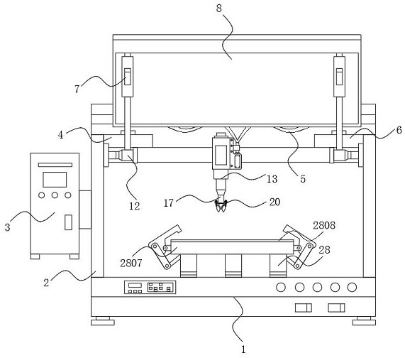
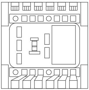
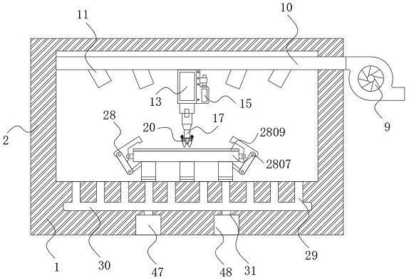
Triaxial sensor production equipment with positioning etching function

A technology of axis sensor and production equipment, which is applied in semiconductor/solid-state device manufacturing, electrical components, circuits, etc., can solve problems such as increasing production costs, difficulty in ensuring absolute verticality, and hidden dangers of user operation safety, so as to save production costs, Fast and efficient classification and collection, low production and maintenance costs

Inactive Publication Date: 2021-01-29
东莞市史雷帝三维数控科技有限公司
View PDF0 Cites 2 Cited by
  • Summary
  • Abstract
  • Description
  • Claims
  • Application Information

AI Technical Summary

Problems solved by technology

[0003] The common problems of the existing three-axis sensor production equipment are: the smooth flow of the spray pipe of the etching equipment is one of the necessary conditions to ensure the uniformity of etching, and the equipment personnel mostly use visual inspection when positioning and installing the spray head To ensure the verticality, it is very time-consuming by visual inspection, and it is difficult to ensure absolute verticality, which affects the spraying effect of the spray pipe. At the same time, the atomization of the existing spray pipe equipment has the disadvantage of small water diffusion area. In addition, the existing etching The equipment cannot handle the waste acid and coolant generated in the processing process, which increases the production cost and causes pollution to the production environment and hidden dangers to the user's operation safety

Method used


Image

  • Triaxial sensor production equipment with positioning etching function
  • Triaxial sensor production equipment with positioning etching function
  • Triaxial sensor production equipment with positioning etching function

Examples


Embodiment Construction

[0032] The following will clearly and completely describe the technical solutions in the embodiments of the present invention with reference to the accompanying drawings in the embodiments of the present invention. Obviously, the described embodiments are only some, not all, embodiments of the present invention.

[0033] In the description of the present invention, unless otherwise stated, the meaning of "plurality" is two or more; the terms "upper", "lower", "left", "right", "inner", "outer" , "front end", "rear end", "head", "tail", etc. indicate the orientation or positional relationship based on the orientation or positional relationship shown in the drawings, and are only for the convenience of describing the present invention and simplifying the description, rather than Indicates or implies that the device or element referred to must have a particular orientation, be constructed and operate in a particular orientation, and therefore should not be construed as limiting the...


PUM


Abstract

The invention discloses triaxial sensor production equipment with a positioning etching function, and relates to the technical field of electronic part production, in particular the equipment comprises a base, a spraying mechanism, a self-locking limiting mechanism, a synchronous lifting mechanism and a flow control mechanism, supports are arranged on the two sides of the base, and a spraying headis arranged at the end, away from a guide column, of a positioning ring. According to the triaxial sensor production equipment with the positioning etching function, through the arrangement of the spraying mechanism and the self-locking limiting mechanism, the problem that when equipment personnel conduct spraying head installation, due to lack of accurate guiding positioning, most of spraying heads are ensured to be perpendicular in a manual visual inspection mode is solved; the self-locking limiting mechanism can achieve rapid butt joint of the guide column and the spraying head through thepositioning ring in a clear guiding mode, locking of the rotor wing and the positioning ring can be rapidly achieved; meanwhile, abnormal falling between the spraying head and the main body in the working process is prevented through the self-locking structure, the unlocking process under the controllable condition is rapid, easy and convenient, and applicability is higher.

Description

technical field [0001] The invention relates to the technical field of electronic parts production, in particular to a three-axis sensor production equipment with positioning etching function. Background technique [0002] With the development of the times, mobile phones play a very important role in all aspects of people's daily life, and among the components of mobile phones, the three-axis acceleration sensor is recognized as the accelerator of most technologies such as the heart of WeChat steps. There are three dimensions to determine the direction of acceleration, the precision is very high, and the power consumption is almost negligible, so it is very powerful. This feature determines that it needs to maintain absolute machining accuracy during machining, which is an item of product design and machining accuracy. ordeal. [0003] The common problems of the existing three-axis sensor production equipment are: the smooth flow of the spray pipe of the etching equipment i...

Claims


Application Information

Patent Timeline
IPC IPC(8): H01L21/67H01L21/683
CPCH01L21/67034H01L21/67051H01L21/6708H01L21/683
Inventor 黄红梅孙锦民陈晨
Owner 东莞市史雷帝三维数控科技有限公司
Why Eureka
Try Eureka