
ASE light source constant power control device and method

A technology of optical power control and constant power, which is applied in the field of ASE light source constant power control devices, can solve problems such as changes in driving current and poor performance of light sources, achieve smooth temperature changes, ensure the quality and performance of light sources, and reduce output instability Effect

Active Publication Date: 2021-01-29
YANGTZE OPTICAL FIBRE & CABLE CO LTD
View PDF10 Cites 2 Cited by
  • Summary
  • Abstract
  • Description
  • Claims
  • Application Information

AI Technical Summary

Problems solved by technology

[0005] For the above defects or improvement needs of the prior art, the present invention provides a constant power control device and method for an ASE light source. This solves the technical problem of poor performance of the light source caused by the change of the driving current of the existing pump laser

Method used


Image

  • ASE light source constant power control device and method
  • ASE light source constant power control device and method
  • ASE light source constant power control device and method

Examples


Embodiment 1

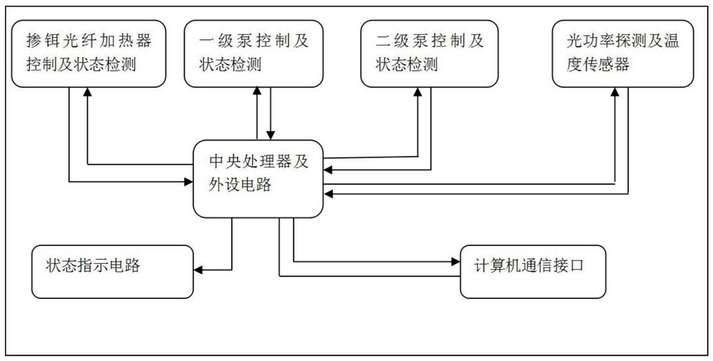
[0053] The ASE light source constant power control device provided in this embodiment, such as figure 1 shown, including:

[0054] Core circuit and status monitoring circuit, including:

[0055] The central processing unit and peripheral circuits are used for control and state detection; the central processing unit and peripheral circuits are composed of a high-speed micro-control processor (MCU), a minimum power supply circuit unit of the processor, and high-speed DA, AD, PWM and processing Composed of device IO ports, it is the core part of the control, detection and acquisition circuit module.

[0056] The control and state detection circuit of the primary pump;

[0057] Secondary pump control and state detection circuit;

[0058] Erbium-doped fiber heater control and state monitoring detection circuit;

[0059] Power detection or temperature sensor circuit;

[0060] computer communication interface;

[0061] status indication circuit.

[0062] The erbium-doped optic...

Embodiment 2

[0073] The working process of the ASE light source constant power control device provided in Embodiment 1 is as follows:

[0074] Power-on self-test, the system automatically detects the initial state of each pump module, the state of the constant current source drive circuit, and the state of the output optical power, and controls the working status indicating circuit to display the self-test result. If the self-test fails, the computer is not allowed to control The circuit system is operated, and the computer is allowed to operate the control system after the self-test is passed;

[0075] Set the target value of the constant temperature fiber optic heater and the constant power value of the ASE light source required by the user through the computer, and automatically trigger the power signal acquisition of the optical power circuit after the pump is turned on, and the temperature signal acquisition and transmission to the PID controller; the software PID (proportional-integra...


PUM


Abstract

The invention discloses an ASE light source constant power control device and method. The device comprises an erbium-doped optical fiber heat preservation box, an erbium-doped optical fiber heater, anerbium-doped optical fiber temperature detector and a heat preservation box temperature control module. The method comprises the following steps: controlling the temperature of the erbium-doped optical fiber: placing the erbium-doped optical fiber in a heat preservation environment, detecting the environment temperature, and controlling the environment temperature to be the working temperature ofthe erbium-doped optical fiber between 50 DEG C and 54 DEG C. By controlling the working temperature of the erbium-doped fiber, the working temperature change of the erbium-doped fiber is kept gentle, the output instability of the ASE light source is fundamentally reduced, and the quality and performance of the light source are ensured. Constant power output of the pump light is effectively maintained by matching with power control of the pump light of each stage, the change rate is small, and the light performance is high.

Description

technical field [0001] The invention belongs to the field of high-performance pump laser control, and more specifically relates to an ASE (Amplified Spontaneous Emission, amplified spontaneous emission, referred to as ASE) light source constant power control device and method. Background technique [0002] With the rapid development of optical communication technology, optical network devices, modules and subsystem products for high-speed communication and data communication applied on optical networks have gradually developed, and as the production inspection of optical network products such as optical devices, optical modules and subsystems , fiber optic sensing systems and institutions and scientific research machines; accurate and stable ASE light sources are essential. [0003] Especially in the construction of core network and backbone network. The stable optical power output of a high-performance pump laser has an important impact on the performance of data transmiss...

Claims


Application Information

Patent Timeline
Patent Type & Authority Applications(China)
IPC IPC(8): H01S3/13H01S3/131H04B10/564
CPCH01S3/13013H01S3/1312H01S3/13017H01S3/1317H01S3/1305H04B10/564
Inventor 黄正武
Owner YANGTZE OPTICAL FIBRE & CABLE CO LTD
Learn More