Direct-conveying type semi-automatic feeding mechanical device

A mechanical device and semi-automatic technology, applied in metal processing equipment, welding equipment, manufacturing tools, etc., can solve the problems of waste products, reduced cutting accuracy, pipe deformation, etc., to achieve the effect of protecting workers' safety, stable mechanical operation, and avoiding adjustments

Pending Publication Date: 2021-02-02
ZHEJIANG JINAOLAN MASCH TOOL CO LTD
View PDF0 Cites 0 Cited by
  • Summary
  • Abstract
  • Description
  • Claims
  • Application Information

AI Technical Summary

Problems solved by technology

If the length of the pipe is long, it may cause deformation of the pipe, which reduces the cutting accuracy and leads to waste

Method used


Image

  • Direct-conveying type semi-automatic feeding mechanical device
  • Direct-conveying type semi-automatic feeding mechanical device
  • Direct-conveying type semi-automatic feeding mechanical device

Examples


Embodiment Construction

[0033] The technical solutions of the various embodiments of the present invention will be clearly and completely described below in conjunction with the accompanying drawings. Apparently, the described embodiments are only some of the embodiments of the present invention, not all of them. Based on the embodiments of the present invention, all other embodiments obtained by persons of ordinary skill in the art without creative work are within the protection scope of the present invention.

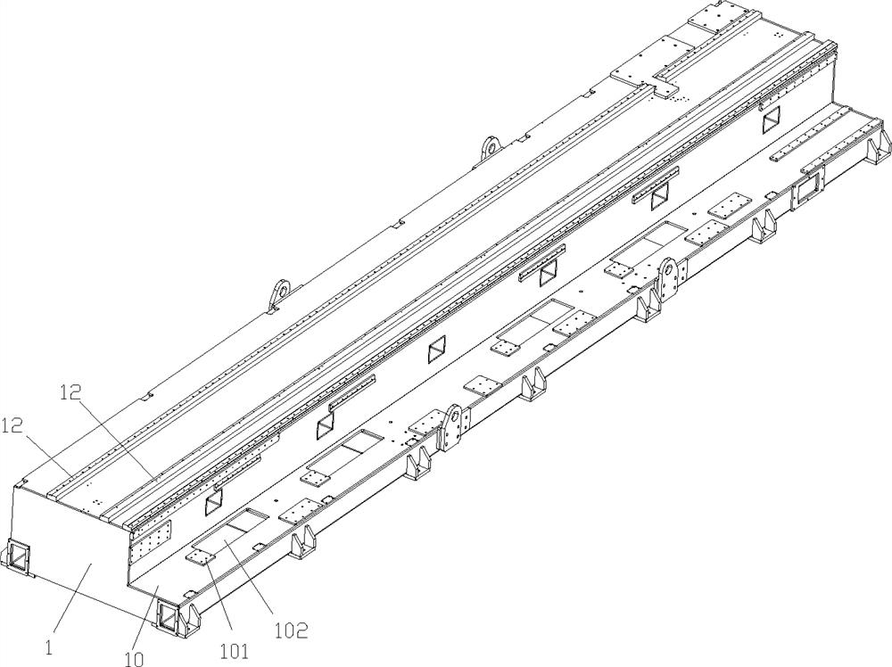
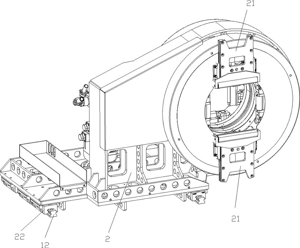
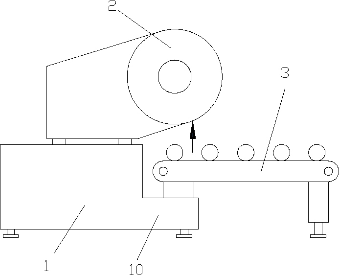
[0034] like Figure 1 to Figure 12As shown, the direct feeding semi-automatic feeding mechanical device includes a bed body 1, a bed attachment 10 is provided on the side of the bed body 1, a chuck 2 is provided on the bed body 1, and a bed attachment 10 is provided with Feeding assembly 11, several floating support assemblies 3, pipe fitting pushing mechanism 6 and feeding mechanism 7, feeding assembly 11, floating supporting assembly 3, pipe fitting pushing mechanism 6 and feeding mechanis...


PUM


Abstract

The invention discloses a direct-conveying type semi-automatic feeding mechanical device. The device comprises a lathe bed body, a lathe bed appendage is arranged on the side edge of the lathe bed body, a chuck is arranged on the lathe bed body, a feeding assembly, a plurality of floating supporting assemblies, a pipe pushing mechanism and a conveying mechanism are arranged on the lathe bed appendage, the feeding assembly, the floating supporting assemblies, the pipe pushing mechanism and the conveying mechanism are matched with one another to conduct feeding and conveying work, and the chuckclamps fed pipes. The direct-conveying type semi-automatic feeding mechanical device is stable in mechanical operation, firm and stable in structure and more convenient and visual to operate, an automatic feeding mode is adopted, clamped pipes can be automatically centered, manual adjustment is avoided, manual intervention is removed, the safety of workers can be protected, the feeding period is shortened, and therefore the production efficiency is improved.

Description

technical field [0001] The invention relates to a direct feeding semi-automatic feeding mechanical device. Background technique [0002] Among the existing metal laser cutting processing equipment, the automatic loading and unloading pipe cutting machine is a kind of automatic pipe cutting equipment that has quietly emerged in recent years. It can independently complete the loading and unloading of pipes without manual placement. Existing pipe cutting machines generally have two types of bed structures, one is a gantry structure, and the other is a wall-mounted structure. In the pipe cutting machine of the existing gantry machine tool, the chuck is located at the center of the guide rail, so the operation is relatively stable. However, it is difficult to achieve zero tailings, and the material waste is huge. There are many feeding logic actions and it takes a long time, so the failure rate is high. Due to the excessive displacement action, it is easy to cause scratches on...

Claims


Application Information

Patent Timeline
Patent Type & Authority Applications(China)
IPC IPC(8): B23K26/02B23K26/38B23K26/70
CPCB23K26/02B23K26/38B23K26/702
Inventor 吕时广郑群强陈勇良张天伟王静王灵英叶建林
Owner ZHEJIANG JINAOLAN MASCH TOOL CO LTD
Why Eureka
Try Eureka