Improved narrow-runner turbine

A narrow channel, improved technology, applied in the field of narrow channel turbines, to achieve the effect of reducing energy consumption, broadening applications, and improving efficiency

Pending Publication Date: 2021-02-02
时剑
View PDF0 Cites 0 Cited by
  • Summary
  • Abstract
  • Description
  • Claims
  • Application Information

AI Technical Summary

Problems solved by technology

Multi

Method used


Image

  • Improved narrow-runner turbine

Examples


Example Embodiment

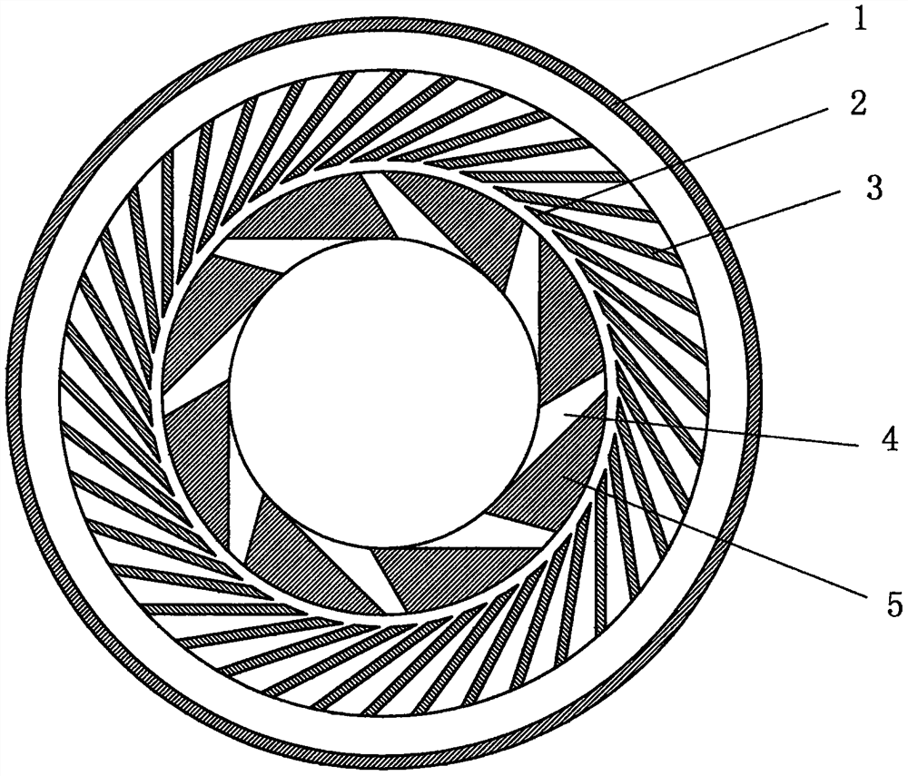
[0008] In the figure, there is a fluid channel (4) on the turbine rotor (5), the flow section of the fluid channel (4) gradually shrinks from the inside to the outside and becomes smaller, and the periphery of the turbine rotor (5) is arranged with diffuser blades (3) , one end of the diffuser blade (3) close to the rotor is tangent to the inner circle of the diffuser to form a diffuser blade oblique angle (2), and the outside of the diffuser is a housing (1).

[0009] When working, the turbine rotor (5) is driven by an external force to rotate at a high speed, and the fluid is sucked in from the middle of the turbine rotor (5), and then sprayed into the diffuser through the fluid channel (4) to decelerate and boost the pressure, and then flows into the housing (1).

[0010] The present invention does not limit the shape of the casing (1), which may be a volute, a pipeline or a pressure vessel, etc., all of which are within the protection scope of the present invention.


PUM


Abstract

An improved narrow-runner turbine comprises a shell, a diffuser and a turbine rotor, the turbine rotor is annular, a fluid channel is formed in the annular rotor, and the flowing section of the fluidchannel is gradually shrunk and decreased from inside to outside, so that fluid sucked by the turbine rotor at a high rotating speed is sealed in the rotor; and the fluid is compressed and filled in the radial direction under the action of centrifugal force, cavitation or surge is avoided, and the fluid is sprayed out only from small holes in the tail end and matched with the diffuser to achieve high lift under small flow. The efficiency of a centrifugal pump can be improved under the working conditions of small flow and high lift, cavitation is not generated at high speed, a centrifugal compressor can reach a high pressure ratio at small flow, and surge is not generated at high speed. The application of an impeller type fluid conveying mechanism is broadened, and energy consumption is reduced.

Description

[0001] Technical field [0002] The invention relates to a narrow channel turbine, which belongs to the technical field of fluid machinery. Background technique [0003] Existing impeller-type fluid delivery mechanisms such as centrifugal pumps have low efficiency under the condition of small flow and high head, and at the same time, cavitation is easy to occur at high speed. Surge. Therefore, the use of the impeller type fluid conveying mechanism is limited, and the energy consumption is increased. Contents of the invention [0004] In order to overcome the deficiencies in the prior art, the present invention provides an improved narrow channel turbine, which includes a casing, a diffuser and a turbine rotor, the turbine rotor is annular, and the annular rotor is provided with Fluid channel, the flow section of the fluid channel gradually shrinks from the inside to the outside, so that the fluid sucked by the turbine rotor at high speed is sealed in the rotor, and the flu...

Claims


Application Information

Patent Timeline
IPC IPC(8): F04D29/28F04D29/44F04D29/66
CPCF04D29/284F04D29/444F04D29/666
Inventor 时剑
Owner 时剑
Why Eureka
Try Eureka