Flat plate type laser and method for improving optical power density

A laser, flat-panel technology, applied in the coupling of optical waveguides, light guides, optics, etc., can solve problems such as the decrease of optical power density, and achieve the effect of reducing the volume, reducing the volume per unit power, and improving the optical power density.

Inactive Publication Date: 2021-02-02
Shandong Huaguang Optoelectronics Co. Ltd.
View PDF7 Cites 3 Cited by
  • Summary
  • Abstract
  • Description
  • Claims
  • Application Information

AI Technical Summary

Problems solved by technology

[0005] Aiming at the deficiencies of the prior art, the present invention provides a flat-panel laser and a method for increasing the optical power density to solve the problem that the light spot has obvious differences in the direction of the fast and slow axes, resulting in a decrease in the optical power density

Method used


Image

  • Flat plate type laser and method for improving optical power density
  • Flat plate type laser and method for improving optical power density
  • Flat plate type laser and method for improving optical power density

Examples


Embodiment 1

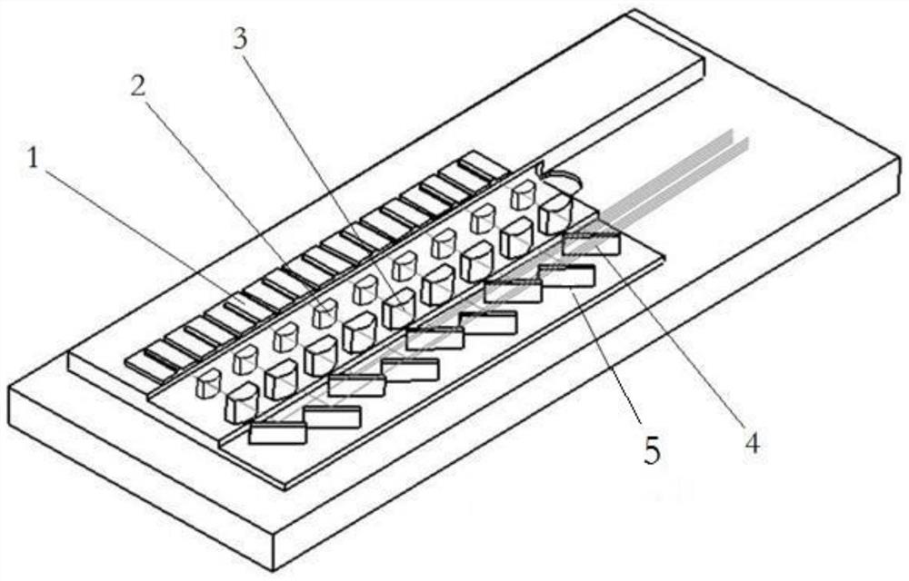
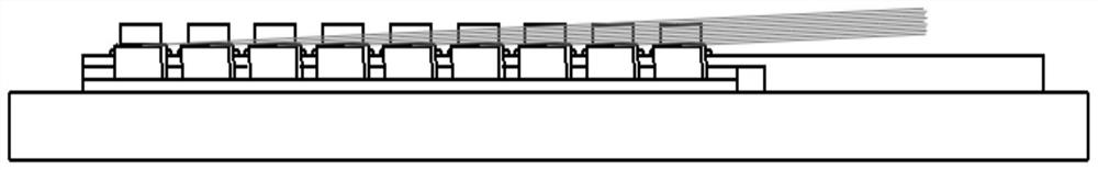
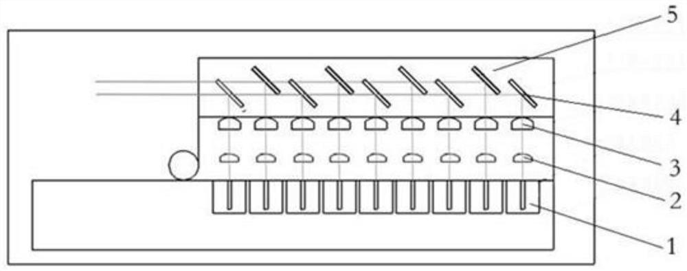
[0032] The reflectors include a first row of reflectors and a second row of reflectors, the first row of reflectors and the second row of reflectors are arranged alternately, the central axes of the first row of reflectors and the second row of reflectors do not coincide, and this In the scheme, the far-field spot of the laser beam is hit at one point, and the near-field spot is divided into two rows. There are two types of mirror adjustments. One is the outermost mirror, called the second row of mirrors. After adjustment, adjust the inner mirror, that is, the first row of mirrors 4. A first row of reflectors and a second row of reflectors are arranged alternately. Because the two types of reflectors have two rows of near-field spots, the actual arrangement of the reflectors is also divided into two rows. The laser reflectors with near-field spots in the same row are in the same row. The beam passes through the two rows of mirrors without blocking each other, so the equivalen...

Embodiment 2

[0034] When the number of chips in the laser is large, when the two rows of light spots cannot balance the light spots in the direction of the fast and slow axes, there may be N=3. At this time, three rows of mirrors are arranged alternately. After the laser beam passes through the focusing lens, three rows of light spots are formed in the near field. When the light spot is arranged, the elevation angle of the reflector is further reduced, and the beam density is further increased.

Embodiment 3

[0036] According to a flat-panel laser, a flat-panel laser and a method for increasing optical power density are also provided:

[0037] (1) The laser diodes are arranged in a single row on the bottom plate;

[0038] (2) The light beam emitted by each laser diode is first collimated by the fast-axis collimating lens, and the light beam becomes parallel light in the fast-axis direction, that is, the direction perpendicular to the laser chip;

[0039] (3) The light beam passes through the fast axis collimating lens and then passes through the slow axis collimating lens, and the light beam becomes parallel light in the direction of the slow axis, that is, along the direction of the chip;

[0040] (4) After the fast and slow axes are collimated, the beam is deflected by 90 degrees through the mirror;

[0041] (5) The elevation angle of the first row of reflectors is the same as that of the second row of reflectors, and they are arranged on the base plate at different optical dist...


PUM


Abstract

The invention discloses a flat plate type laser and a method for improving optical power density, and the flat plate type laser comprises a laser bottom plate, the laser bottom plate is provided witha laser chip, and the laser chip is sequentially provided with a fast axis collimating lens, a slow axis collimating lens and a reflector in the optical path direction; for the multi-beam flat plate type laser, the scheme can obviously balance the angle of the laser beam entering the optical fiber in the fast and slow axis direction, and after a single-row reflector is changed into a double-row reflector, the height of the beam is almost reduced to half of the height of the original beam so that the finally formed near-field light spot is closer to a square; therefore, the utilization rate ofthe focusing lens can be greatly improved, the light beam density is improved, the scheme is simple and easy to operate, the size of the laser can be reduced to a greater extent, and the unit power size of the laser is reduced.

Description

technical field [0001] The invention relates to the field of semiconductor lasers, in particular to a flat-plate laser and a method for increasing optical power density. Background technique [0002] Nowadays, the development of production and life requires more and more high-power lasers, and improving the optical power density of lasers has become one of the goals that everyone is competing for. At present, due to the obvious difference in the divergence angle of the fast and slow axes of the laser, there are obvious differences in the light spots in the direction of the fast and slow axes. When the number of lasers exceeds a certain value, the laser spot imbalance in the fast and slow axis direction will easily lead to an increase in numerical aperture and a decrease in optical power density. Spatial dimension expansion, polarization beam combining, and coupling lens combination have become commonly used methods to increase the optical power density of lasers. [0003] ...

Claims


Application Information

Patent Timeline
Patent Type & Authority Applications(China)
IPC IPC(8): G02B6/42G02B27/09G02B27/10G02B27/48
CPCG02B6/4204G02B6/4214G02B27/0922G02B27/0961G02B27/0977G02B27/106G02B27/48
Inventor 于果蕾王美美开北超刘成成邵慧慧
Owner Shandong Huaguang Optoelectronics Co. Ltd.
Why Eureka
Try Eureka