Supercharge Your Innovation With Domain-Expert AI Agents!

Super capacitor power cache circuit

A technology of supercapacitors and supercapacitors, applied in battery circuit devices, circuit devices, safety/protection circuits, etc., can solve problems such as unsatisfactory fast response, achieve the effects of increasing battery life, good discharge effect, and reducing direct waste

Pending Publication Date: 2021-02-02
UNIV OF SCI & TECH OF CHINA
View PDF0 Cites 0 Cited by
  • Summary
  • Abstract
  • Description
  • Claims
  • Application Information

AI Technical Summary

Problems solved by technology

[0003] Usually at this stage, some methods such as soft start are used to slow down the impact on the battery, but for the requirements of robots and industrial control, these methods are still unable to meet the requirements of rapid response

Method used


Image

  • Super capacitor power cache circuit
  • Super capacitor power cache circuit
  • Super capacitor power cache circuit

Examples


Embodiment Construction

[0039]The present invention will be described in detail below with reference to the drawings and embodiments.

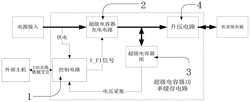
[0040]Such asfigure 1 As shown, a super capacitor power buffer circuit of the present invention includes a control circuit 1, a super capacitor charging circuit 2, a super capacitor bank 3, and a boost circuit 4.

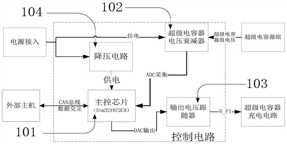
[0041]The super capacitor voltage attenuator 102 in the control circuit 1 attenuates the voltage of the super capacitor bank 3 to a range that can be collected by the main control chip 101 for ADC collection.

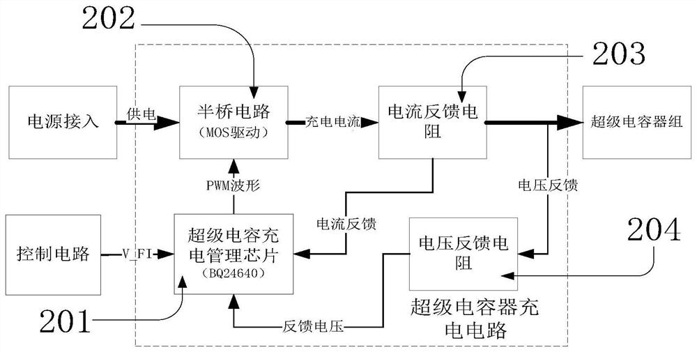
[0042]The control circuit 1 uses the maximum power information sent by the CAN bus and the current super capacitor bank voltage to calculate the required current limit information V_FI in real time. Its expression isRfIs the resistance value of the current feedback resistor 203, P is the maximum power information sent from the CAN bus, where 20 is the sampling voltage amplification factor inside the BQ24640 chip, and V is the super capacitor collected by the main ...


PUM


Abstract

The invention relates to a super capacitor power cache circuit which comprises a control circuit, a super capacitor charging circuit, a super capacitor bank and a boost circuit, the control circuit isresponsible for detecting the real-time voltage of a super capacitor so as to output maximum current information (V_FI) which can be used for receiving in the form of a voltage signal; the super capacitor charging circuit performs specific power charging on the super capacitor bank according to the V_FI information provided by the control circuit; the boost circuit outputs power by using energy provided by the super capacitor, and since the charging power of the super capacitor is constant and the super capacitor can buffer the energy, when the system load is large, the impact of the high power consumption load on a battery at the moment does not need to be worried, thereby realizing the buffer of the power supply energy. And in addition, the boost circuit can charge reverse energy from the output end back to the super capacitor bank, so that the energy recovery of the system load is realized.

Description

Technical field[0001]The invention relates to the field of robots and industrial control, and can be applied to scenarios of power buffering or energy recovery.Background technique[0002]With the development of robots and industrial technology, higher requirements are put forward for the control of battery power. In some specific fields, a stable low-power output of the battery is required to maximize the energy utilization of the battery, but usually the load fluctuates greatly, sometimes even at high power or no load for a long time. To this end, it is necessary to add a certain power compensation mechanism, so that the power at no load (or energy recovery) can be buffered and released when the load continues to be high, thereby improving the continuous power supply capability of the battery.[0003]Usually at this stage, some methods such as soft start are used to slow down the impact on the battery, but for the requirements of robots and industrial control, these methods have not b...

Claims


Application Information

Patent Timeline
IPC IPC(8): H02J7/00H02J7/34H02M1/34
CPCH02J7/0029H02J7/0036H02J7/007H02J7/345H02M1/34H02J2207/30H02J2207/50
Inventor 黄芳胜贺小焕董二宝倪向贵张世武连厚泉鲍本坤戴童欣刘煜川
Owner UNIV OF SCI & TECH OF CHINA
Features
  • R&D
  • Intellectual Property
  • Life Sciences
  • Materials
  • Tech Scout
  • Unparalleled Data Quality
  • Higher Quality Content
  • 60% Fewer Hallucinations
Learn More