Filter pressing device for producing nanometer calcium carbonate
A nano-calcium carbonate and bottom plate technology is applied in the field of filter press devices, which can solve the problems that the plate frame and filter cloth are not suitable for cleaning, and achieve the effect of stable efficiency and simple structure.
- Summary
- Abstract
- Description
- Claims
- Application Information
AI Technical Summary
Problems solved by technology
Method used
Image
Examples
Embodiment 1
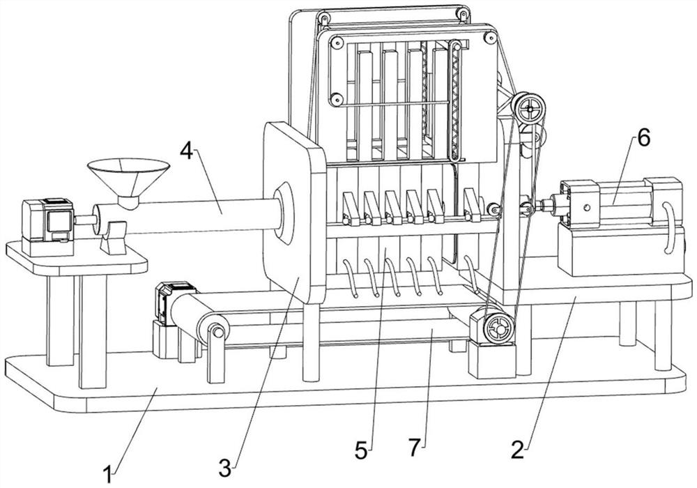
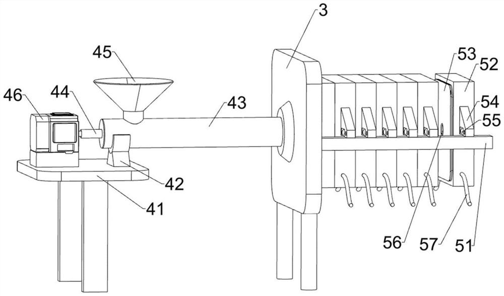
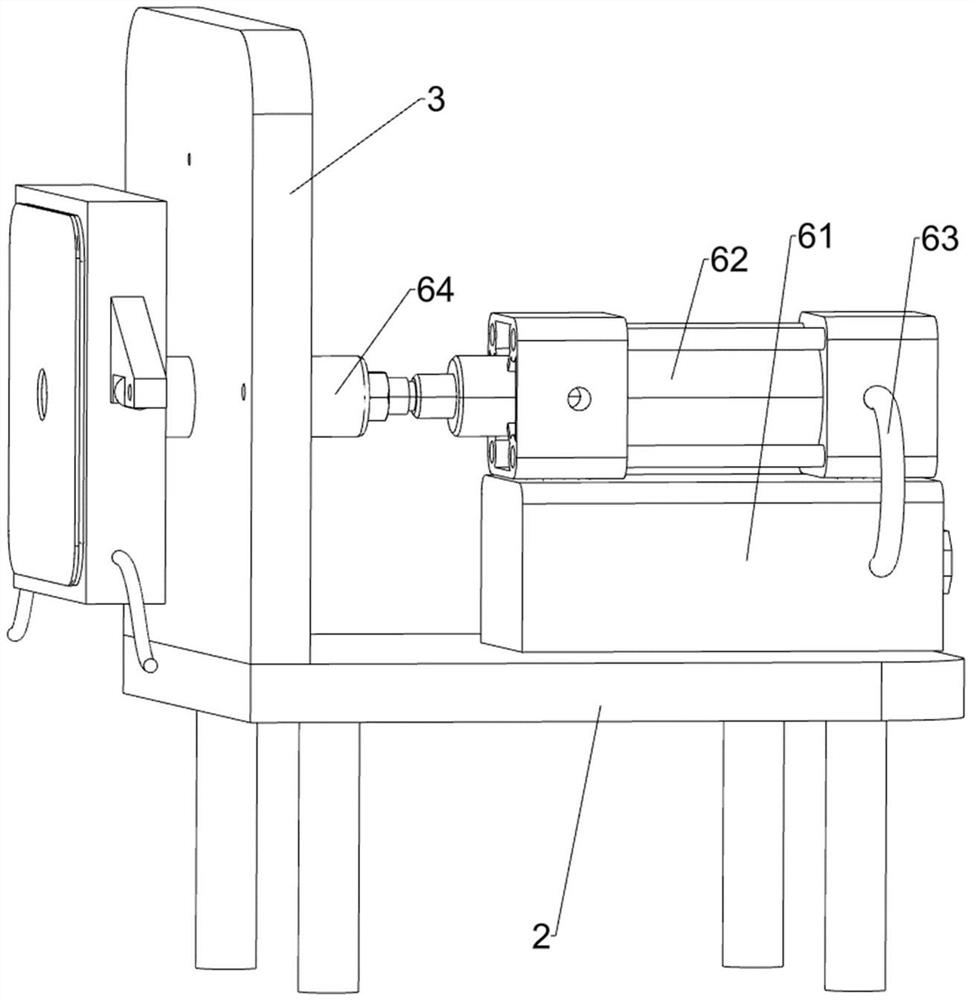
[0028] like figure 1 , figure 2 , image 3 and Figure 4 Shown, a kind of nano-calcium carbonate production press filter device includes base plate 1, first support frame 2, support plate 3, feed mechanism 4, filter mechanism 5, pressing mechanism 6 and discharge mechanism 7, base plate 1 The first support frame 2 is arranged on the upper right side, and two support plates 3 are arranged at intervals in the middle of the bottom plate 1. One support plate 3 is connected to the left side of the top of the first support frame 2, and the other is arranged on the bottom plate 1 at a certain distance. 1 is provided with a feeding mechanism 4 on the side away from the first support frame 2, a filter mechanism 5 is provided between the two support plates 3, a pressing mechanism 6 is provided on the top of the first support frame 2, and an outlet mechanism 6 is provided at the upper middle of the bottom plate 1. Material mechanism7.
[0029] The feeding mechanism 4 includes a seco...
Embodiment 2
[0035] like Figure 4 , Figure 5 , Image 6 and Figure 7 As shown, on the basis of Embodiment 1, it also includes a reduction box 8, a second bearing seat 10, a second rotating shaft 11, a pulley assembly 12, a first bobbin 13, a first fixed wheel assembly 14, a first Cable 15 and ball 16, the front end of the first rotating shaft 72 on the right is provided with a reduction box 8, the input shaft of the reduction box 8 is connected with the runner 73 and then the output torque, the reduction box 8 is connected with the bottom plate 1, the support on the right side The top of the plate 3 is symmetrically arranged with a second bearing housing 10 front and back, and the second rotating shaft 11 is rotatably mounted on the two second bearing housings 10. The output shaft of the reduction box 8 is connected to the second rotating shaft 11 through a pulley assembly 12, and the second rotating shaft 11 The first bobbin 13 is installed symmetrically at both ends, the left and r...
Embodiment 3
[0039] like Figure 8 As shown, on the basis of Embodiment 2, it also includes a pressing rod 28, a second connecting pin 29, a second guide groove 30, a third fixed wheel assembly 31, a third bearing seat 32, a third rotating shaft 33, a first Three bobbins 34, a rotating handle 35 and a third cable 36, a pressure bar 28 is arranged on the top of the cross bar 24, and a second connecting pin 29 is arranged on the left and right symmetrically on the front side of the pressure bar 28, and the rear side of the front guide groove plate 17 The left and right edges are symmetrically provided with second guide grooves 30, and the pressure rod 28 is slidably connected in the second guide groove 30 through the second connecting pin 29. Two third fixed wheel assemblies 31 are symmetrically arranged at both ends of the top of the pressure rod 28. A third bearing seat 32 is arranged on the right side of the right support plate 3, and a third rotating shaft 33 is rotatably mounted on the ...
PUM
 Abstract
Description
Claims
Application Information
 - R&D
- Intellectual Property
- Life Sciences
- Materials
- Tech Scout
- Unparalleled Data Quality
- Higher Quality Content
- 60% Fewer Hallucinations
Browse by: Latest US Patents, China's latest patents, Technical Efficacy Thesaurus, Application Domain, Technology Topic, Popular Technical Reports.
© 2025 PatSnap. All rights reserved.Legal|Privacy policy|Modern Slavery Act Transparency Statement|Sitemap|About US| Contact US: help@patsnap.com


