
Production equipment with hole diameter detection function and for exhaust manifold interface flange

A technology of interface flange and exhaust manifold, which is applied in the field of production equipment with aperture detection function, can solve the problem that the aperture of the interface flange cannot be controlled very accurately, the interface flange exhaust manifold is consistent, and the product cannot be guaranteed Surface smoothness and other issues to achieve the effect of improving processing efficiency and product quality, improving pass rate, improving processing efficiency and product quality

Inactive Publication Date: 2021-02-09
东莞市达盛机电设计有限公司
View PDF0 Cites 1 Cited by
  • Summary
  • Abstract
  • Description
  • Claims
  • Application Information

AI Technical Summary

Problems solved by technology

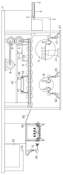
[0004] Aiming at the deficiencies of the prior art, the present invention provides a production equipment with aperture detection function for the exhaust manifold interface flange, which solves the problem that the general interface flange production equipment proposed in the above background technology is often formed by calcination and cannot be formed. Ensure the smoothness of the product surface, and the hole diameter on the interface flange cannot be controlled very precisely, it is easy to make the interface flange not completely match the exhaust manifold when it is welded with the exhaust manifold, resulting in exhaust emissions problem appear

Method used


Image

  • Production equipment with hole diameter detection function and for exhaust manifold interface flange
  • Production equipment with hole diameter detection function and for exhaust manifold interface flange
  • Production equipment with hole diameter detection function and for exhaust manifold interface flange

Examples


Embodiment Construction

[0030] The technical solutions in the embodiments of the present invention will be clearly and completely described below in conjunction with the accompanying drawings in the embodiments of the present invention. Obviously, the described embodiments are only some of the embodiments of the present invention, not all of them. Based on The embodiments of the present invention and all other embodiments obtained by persons of ordinary skill in the art without making creative efforts belong to the protection scope of the present invention.

[0031] In the description of the present invention, unless otherwise stated, the meaning of "plurality" is two or more; the terms "upper", "lower", "left", "right", "inner", "outer" , "front end", "rear end", "head", "tail", etc. indicate the orientation or positional relationship based on the orientation or positional relationship shown in the drawings, and are only for the convenience of describing the present invention and simplifying the desc...


PUM


Abstract

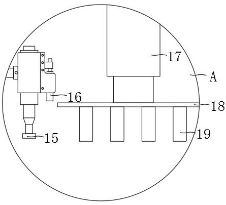
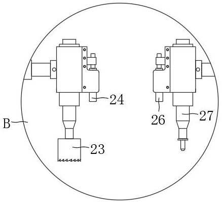
The invention discloses production equipment with a hole diameter detection function and for an exhaust manifold interface flange. The production equipment comprises a bottom disc, a material containing plate is arranged on the upper left portion of the bottom disc, a material pushing plate is arranged on the right portion of a material pushing rod, a half gear is arranged on the right portion ofa material storage bin, multiple rolling shafts are arranged above the half gear, and a motor is arranged on the right portion of the half gear. A lifting rod is arranged above a transverse plate, a first mechanical arm is arranged above a baffle, an edge grinding machine is arranged at the right end of the first mechanical arm, a hydraulic rod is arranged on the right side of a calibrator, four pressing columns are arranged on the lower surface of a pressing plate, a telescopic rod is arranged on the right portion of the lifting rod, a second mechanical arm is arranged above a mechanical hand, and a positioner is arranged on the right side of a hole cutting machine. Compared with existing common exhaust manifold interface flange production equipment, by means of the production equipment with the hole diameter detection function and for the exhaust manifold interface flange, the machining precision during product machining is improved, and the machining efficiency and the product quality are improved.

Description

technical field [0001] The invention relates to the technical field of production of exhaust manifold interface flanges, in particular to a production equipment for exhaust manifold interface flanges with aperture detection function. Background technique [0002] With the development of the times, automobiles have entered thousands of households as a common means of transportation, and among the components of automobiles, the exhaust system plays a very important role, which can discharge the exhaust gas generated in the engine, making the engine It can run normally, and the interface flange is the connection between the exhaust manifold and the engine. Once there is a problem with the interface flange, the exhaust gas cannot be discharged through the exhaust manifold normally, which will affect the normal operation of the engine. [0003] The existing interface flange production equipment is often formed by calcination, which cannot guarantee the smoothness of the product s...

Claims


Application Information

Patent Timeline
Patent Type & Authority Applications(China)
IPC IPC(8): B23P23/04B23Q17/20
CPCB23P23/04B23Q17/20
Inventor 李颖琼刘增铭
Owner 东莞市达盛机电设计有限公司
Learn More