Machine tool

A machine tool and robot technology, applied in the direction of manipulators, metal processing machinery parts, manufacturing tools, etc., can solve problems that cannot be used to combine robots, time-consuming, and non-production time

Pending Publication Date: 2021-02-09
OKUMA CORP
View PDF2 Cites 0 Cited by
  • Summary
  • Abstract
  • Description
  • Claims
  • Application Information

AI Technical Summary

Problems solved by technology

Time consuming replacement of end effectors based on task type resulting in non-productive time spent on processes other than machining
For a typical robot, a large end effector with multiple functions is used; however, such a large end effector is often not available for a robot incorporated inside a machine tool
The structure disclosed in JP2019-98479A also has the limitation that the end effector cannot be freely in any position

Method used


Image

  • Machine tool
  • Machine tool
  • Machine tool

Examples


Embodiment Construction

[0031] Embodiments of the present invention will be described below with reference to the accompanying drawings.

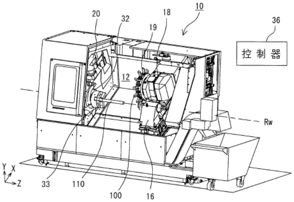
[0032] figure 1 The structure of the machine tool 10 is shown. In the following description, the direction parallel to the workpiece rotation axis Rw of the workpiece spindle 32 is referred to as the Z axis, the direction parallel to the moving direction of the tool post 18 perpendicular to the Z axis is referred to as the X axis, and the direction parallel to the X axis and The direction in which the Z axes are all perpendicular is called the Y axis. On the Z axis, the direction directed from the workpiece spindle 32 to the tailstock 16 is defined as the positive direction; on the X axis, the direction directed from the workpiece spindle 32 to the tool rest 18 is defined as the positive direction; on the Y axis, the upward direction from the workpiece spindle 32 The direction of is defined as positive. In the following description, the expression that the end ...


PUM


Abstract

A machine tool is disclosed. The machine tool includes a robot which is compact and which enables easy use of different end effectors for respective purposes. An internal robot includes a plurality ofjoints that are composed of a base joint and parallel joints, and a plurality of links. The distal end is split into two or more branches, each having a tool changer. An end effector is detachably attachable to each of the tool changers. Rotation of the base joint causes a change between a first tool-following position and a second tool-following position, so that different end effectors are usedfor respective purposes by using an end effector attached to a tool changer in the first tool-following position and using an end effector attached to another tool changer in the second tool-following position.

Description

[0001] Cross-references to related applications [0002] This application claims priority from Japanese Patent Application No. 2019-144867 filed on August 6, 2019, the entire contents of which including specification, claims, drawings and abstract are hereby incorporated by reference Application. technical field [0003] The present invention relates to machine tools, and more particularly to machine tools including internal robots. Background technique [0004] There is a need for further automation of machine tools. One solution is to use robots inside the machine tool. Using a robot enables various tasks; such as attachment or detachment of a tool or a workpiece; such as cleaning of the inner space of a machine tool, the tool, and the workpiece; prevention of chip adhesion; and prevention of chatter of the workpiece. [0005] A structure of a robot is described in JPS59-66589U, which discloses a manipulator comprising: a first arm disposed at right angles to the end of...

Claims


Application Information

Patent Timeline
Patent Type & Authority Applications(China)
IPC IPC(8): B23Q7/04
CPCB23Q7/048B25J15/04B23Q2003/155418B23Q1/5481B23Q3/1554B23Q2003/155428B23Q2003/155453B25J15/0066B23Q7/046B23Q11/10B25J17/02B25J15/0019B23Q7/04
Inventor 森村章一
Owner OKUMA CORP
Why Eureka
Try Eureka