
Ventilation equipment convenient for greenhouse gas emission

A technology for ventilation equipment and greenhouse gases, which is applied to the structural details of gas analyzers, analysis of gas mixtures, instruments, etc., can solve problems such as difficult to move, large volume, loud noise, etc., achieve good sound absorption effect, easy installation and fixation, The effect of easy detection

Pending Publication Date: 2021-02-09
卢永保
View PDF6 Cites 0 Cited by
  • Summary
  • Abstract
  • Description
  • Claims
  • Application Information

AI Technical Summary

Problems solved by technology

[0004] The purpose of the present invention is to provide a kind of ventilating equipment that is convenient for greenhouse gas emission. By setting universal wheels to facilitate movement, the problem that the existing ventilating equipment is large and difficult to move is solved; by setting the noise reduction box, the existing When the equipment is working, it produces a lot of noise, which affects people's lives

Method used


Image

  • Ventilation equipment convenient for greenhouse gas emission
  • Ventilation equipment convenient for greenhouse gas emission
  • Ventilation equipment convenient for greenhouse gas emission

Examples


Embodiment 1

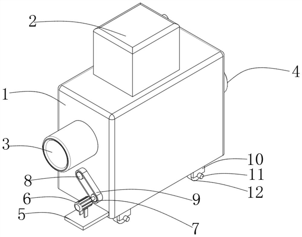
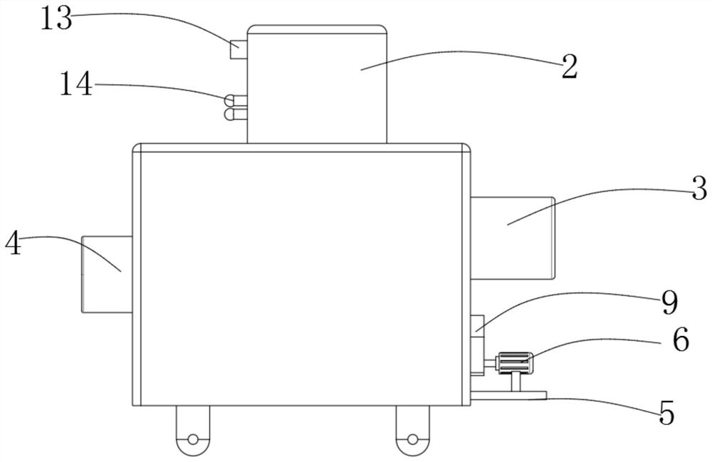
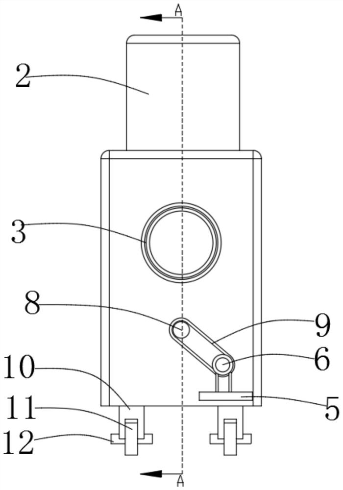
[0038] The following is a specific method for using the ventilation equipment for greenhouse gas emissions: when using the present invention, the equipment should be moved to the corresponding position, fixed by the brake block 11, the air pump 22 is connected to the power supply, and the air pump 22 is connected to the power supply. The gas port 13 extracts gas and detects it through the gas concentration monitoring device 23. When the concentration of greenhouse gases reaches a certain level, the sound and light alarm lamp 14 starts to alarm. At this time, the drive motor 6 is connected to the power supply, so that the driving wheel 7 rotates. Under the action of the rotating belt 9, the driven runner 8 also starts to rotate, and then drives the powerful fan 17 to rotate. Under the action of the powerful fan 17, the gas enters the inside of the gas treatment box 1 through the air intake pipe 3, and is carried out by two layers of absorbing plates. absorbed, and then discharge...

Embodiment 2

[0039] Embodiment 2: It needs to be further explained that a lot of noise will be generated when the equipment is running. At this time, the noise reduction box 21 should be installed inside, slide the second block 33, and then turn the handle 29 to place the first block 30 is installed in the limiting groove 34, and the noise reduction box 21 absorbs the noise through the muffler pipe 36 and the sound wave absorption wall 38.


PUM


Abstract

The invention discloses ventilation equipment convenient for greenhouse gas emission, and relates to the technical field of greenhouse gas emission. The equipment comprises a gas treatment box and a gas detection box, a gas inlet pipe and a gas outlet pipe are arranged on the two surfaces of the gas treatment box correspondingly, a mounting plate is arranged in the gas treatment box, a first absorption plate, a second absorption plate and a noise reduction box are arranged on the bottom face of the mounting plate, sound wave inlets are formed in the two side faces of the noise reduction box, and silencing pipes are mounted on the peripheral side faces of the sound wave inlets; and a sliding cover is arranged on the side face of the inner wall of the noise reduction box, a sound wave absorption wall is arranged in the noise reduction box, and a sucking pump, a gas inlet chuck, a gas concentration detection device and a gas component detection device are arranged in the body detection box. By arranging the gas concentration detection device, the concentration of greenhouse gas can be conveniently detected; two layers of absorption edges are arranged, so that greenhouse gas can be absorbed conveniently; and a sound-light alarm lamp is arranged, when the greenhouse gas reaches a certain concentration, an alarm is given out, and a user is reminded to discharge the greenhouse gas.

Description

technical field [0001] The invention belongs to the field of greenhouse gas discharge, and in particular relates to a ventilating device convenient for greenhouse gas discharge. Background technique [0002] Greenhouse gases refer to some gases in the atmosphere that can absorb long-wave radiation reflected by the bottom surface and re-emit radiation, such as water vapor, carbon dioxide, and most refrigerants. Their effect is to make the Earth's surface warmer, similar to how a greenhouse traps solar radiation and heats the air inside the greenhouse. The effect of this greenhouse gas warming the Earth is called the "greenhouse effect." Water vapor, carbon dioxide, and oxygen Nitrous nitrogen, Freon and methane are the main greenhouse gases in the earth's atmosphere. [0003] With the development of industry, more and more greenhouse gases are produced, followed by the phenomenon of global warming. Most of the existing greenhouse gas ventilation equipment is large in size, d...

Claims


Application Information

Patent Timeline
Patent Type & Authority Applications(China)
IPC IPC(8): G01N33/00
CPCG01N33/0009
Inventor 卢永保
Owner 卢永保
Learn More