
Air path opening and closing combined drying device

A drying device and gas path technology, applied in drying, drying machine, drying gas arrangement, etc., can solve the problems of heat pump system structure complexity, heat pump system stability, reliability decline, etc., to achieve system reliability improvement, The effect of simplification of the structure of the fluorine circuit

Pending Publication Date: 2021-02-12
SHANGHAI BOHAN THERMAL ENERGY TECH CO LTD
View PDF0 Cites 4 Cited by
  • Summary
  • Abstract
  • Description
  • Claims
  • Application Information

AI Technical Summary

Problems solved by technology

[0009] This kind of heat pump system with "one machine, three functions" has added the function of internal dehumidification and external heat removal in addition to the main functions of external heat absorption and internal heating, internal dehumidification and internal heating, and solves the problem of excess heat inside the barn during the yellowing period. Outflow problem, but the structure of the heat pump system is too complicated. On the pipeline between the compressor, the throttle valve and the three heat exchangers, a four-way valve, two solenoid valves, and three one-way valves are installed, resulting in The stability and reliability of the heat pump system are greatly reduced

Method used


Image

  • Air path opening and closing combined drying device
  • Air path opening and closing combined drying device
  • Air path opening and closing combined drying device

Examples


Embodiment 1

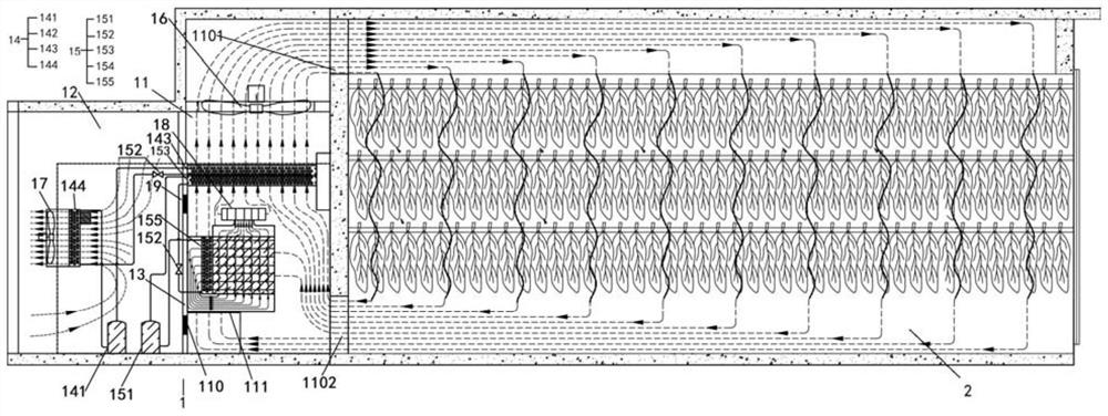
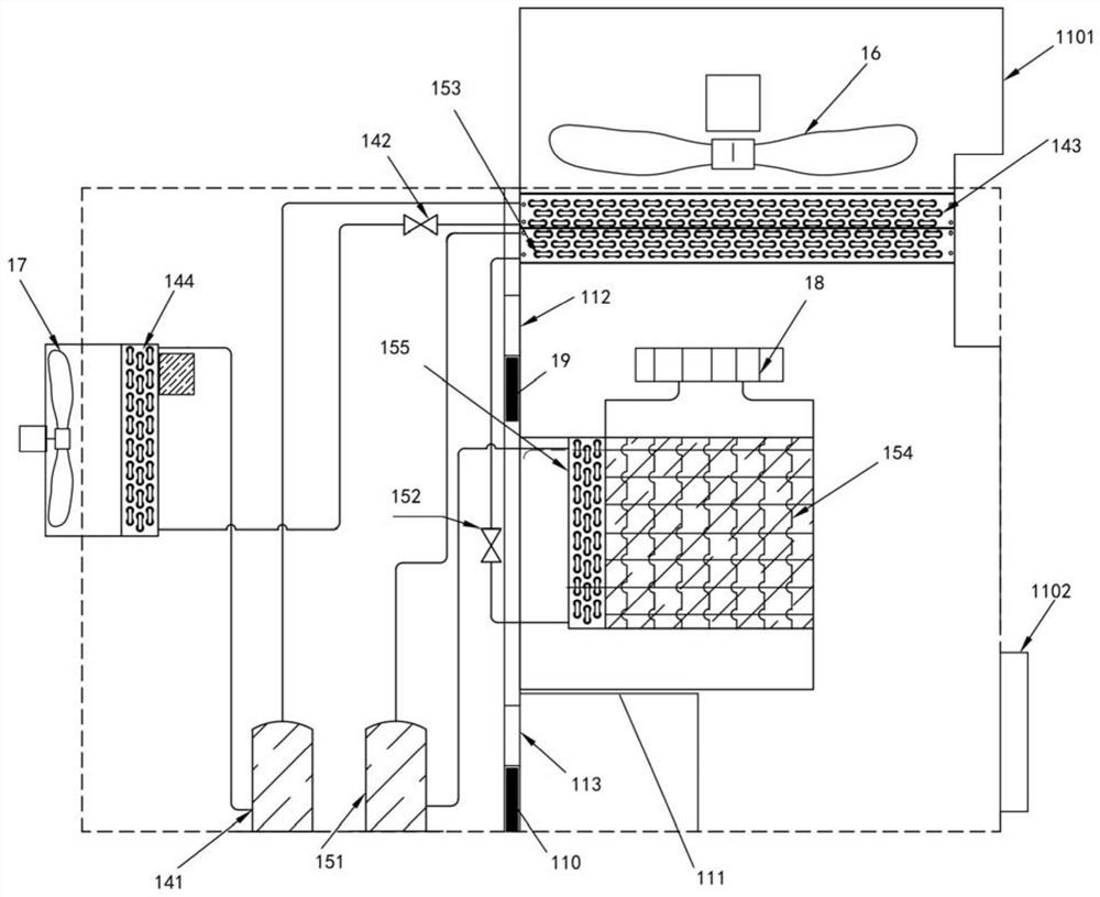
[0061] Please refer to Figure 2 to Figure 9 The drying device provided in this embodiment takes a heat pump unit as an example. This heat pump unit is composed of at least one heat pump unit 15 with internal dehumidification and internal heating and at least one heat pump unit 14 with external heat absorption and internal heating. The heat pump unit 15 for internal dehumidification and internal heating is used for Internal dehumidification and internal heating, external heat absorption and internal heating The heat pump unit 14 is used for external heat absorption and internal heating.

[0062] In this embodiment, the wall of the inner cavity 11 is provided with an air inlet 1102 and an air outlet 1101 for communicating with the barn 2, the air inlet 1102 is located below the inner cavity 11, and the air outlet 1101 is located at the bottom of the inner cavity 11. above. A first fan 16 is provided at the air outlet 1101 .

[0063] The heat pump unit 14 for external heat abs...

Embodiment 2

[0085] The basic principle of this embodiment is the same as that of Embodiment 1, the difference is that in Embodiment 1, the fresh air outlet 112, the moisture discharge outlet 113, the fresh air damper 19, the moisture discharge damper 110 and the driving device are all arranged on the partition 13, while this embodiment Embodiment The fresh air port 112, the moisture discharge port 113, the fresh air damper 19, the humidity discharge damper 110 and the driving device are all arranged on the inner cavity side wall 1103, please refer to Figure 20 In addition to all the advantages of Embodiment 1, this embodiment also has the advantages of being convenient for maintenance and not competing with the outer chamber 12 for fresh air flow when making up fresh air.

Embodiment 3

[0087] Please refer to Figure 10 to Figure 19 In this embodiment, on the basis of Embodiment 1 and Embodiment 2, a dehumidification guide plate 111 is added, that is, in the inner cavity 11, above the dehumidification port 113 and below the inner dehumidification module (that is, dehumidification Between the port 113 and the inner dehumidification module) there is a moisture-discharging guide plate 111 , and the moisture-discharging guide plate 111 is rotatably disposed on the partition 13 or the inner cavity side wall 1103 . When the moisture discharge damper 110 is opened, the moisture discharge guide plate 111 is unfolded; when the moisture discharge damper 110 is closed, the moisture discharge guide plate 111 is retracted.

[0088] Preferably, when the new air port 112, the moisture discharge port 113, the fresh air damper 19, the moisture discharge damper 110 and the driving device are all arranged on the partition 13, the moisture discharge guide plate 111 is also arran...


PUM


Abstract

The invention relates to an air path opening and closing combined drying device, and the device comprises a heating and dehumidifying room, wherein the interior of the heating and dehumidifying room is divided into at least one inner cavity and at least one outer cavity through a partition plate; the outer cavity is communicated with ambient air, and the inner cavity is communicated with a curingbarn to form a circulating channel of drying airflow; the side wall of the inner cavity or the partition plate is further provided with a fresh air opening and a moisture discharging opening. When thedrying airflow is in closed circulation, the fresh air opening and the moisture discharging opening are closed at the same time, and the drying airflow circularly moves in a closed circulation channel formed by the inner cavity and the curing barn; when the drying airflow is partially circulated in an open circuit mode, the fresh air opening and the moisture discharging opening are opened at thesame time, warm and wet return air in the curing barn enters the inner cavity, part of the warm and wet return air entering the inner cavity is discharged out of the inner cavity through the moisturedischarging opening, and meanwhile environment fresh air is supplemented into the inner cavity through the fresh air opening. The method solves the problems that in the yellowing period, cells such asfresh tobacco leaves are still in the aerobic respiration and living body metabolism stages, and the autologous heat productivity of the tobacco leaves is large, so that more heat is generated in thecuring barn, and the dry-bulb temperature exceeds the target value.

Description

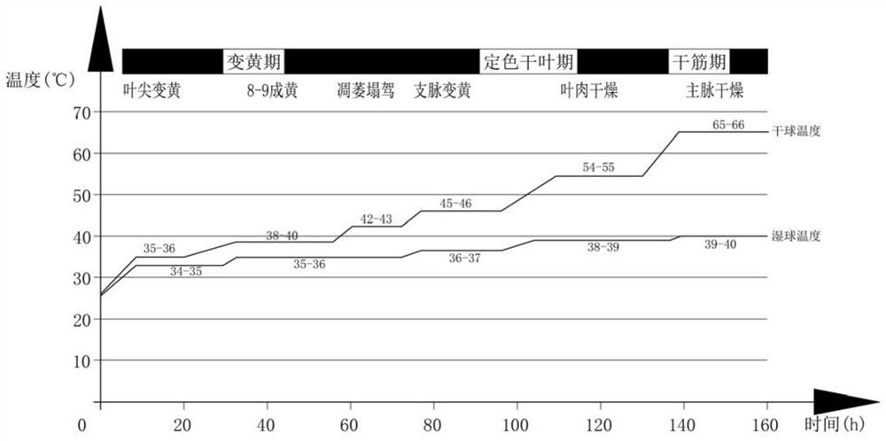
technical field [0001] The invention relates to the technical field of heat pump drying, in particular to a drying device combined with gas path opening and closing. Background technique [0002] Since green development has become the mainstream concept in society, heat pumps have gradually become the leading technology in the drying field of agricultural products, wood, paper, seafood, etc. instead of coal-fired hot air stoves, gas hot air stoves, and oil-fired hot air stoves. [0003] Heat pump drying of tobacco leaves is the focus of heat pump drying of agricultural products. After years of research and development by many heat pump companies, the heat pump technology for tobacco leaf curing has gradually matured. The heat pump tobacco curing room that cooperates with the intensive curing room and insulation board room stipulated in the 2009 National Tobacco Administration Document No. 418 is gradually being promoted in the smoking area. [0004] During the 170-hour baki...

Claims


Application Information

Patent Timeline
IPC IPC(8): A24B3/10F26B21/00F26B21/04F26B21/06F26B21/08
CPCA24B3/10F26B21/00F26B21/002F26B21/04F26B21/06F26B21/086F26B2200/22
Inventor 薛世山刘剑君李成伟韦林林诸葛水明吴飞飞王恒马骥应小勇胡用刘帅帅徐学冲王庆伦
Owner SHANGHAI BOHAN THERMAL ENERGY TECH CO LTD
Learn More