Eureka AIR delivers breakthrough ideas for toughest innovation challenges, trusted by R&D personnel around the world.

Staggered declination type sludge drying device

A drying device and sludge technology, applied in the direction of dehydration/drying/thickened sludge treatment, etc., can solve the problems of low utilization rate of hot air, poor controllability of hot air, complex structure, etc., to save space and reduce floor space , reduce the effect of accumulation

Inactive Publication Date: 2021-02-12
XI AN JIAOTONG UNIV
View PDF10 Cites 1 Cited by
  • Summary
  • Abstract
  • Description
  • Claims
  • Application Information

AI Technical Summary

Problems solved by technology

[0008] The patent application number is 201810564118.5, which is a drying system for quickly drying grains. It adopts a downward-inclining structure. Although its blower fan, sieve holes and other structures can speed up the air flow between the various areas inside the drying chamber, so that each area can be dried The drying effect is relatively uniform, but the controllability of the air path to the hot air is poor, the utilization rate of the hot air is low, the structure is complex, and the energy consumption is large, so the grain drying system and its supporting drying methods are not suitable for Sludge drying that does not need to consider the uniformity of drying quality but should pay more attention to energy saving and drying efficiency

Method used


Image

  • Staggered declination type sludge drying device
  • Staggered declination type sludge drying device
  • Staggered declination type sludge drying device

Examples


Embodiment Construction

[0038] The present invention will be described in further detail below in conjunction with accompanying drawing, and its content is explanation of the present invention rather than limitation:

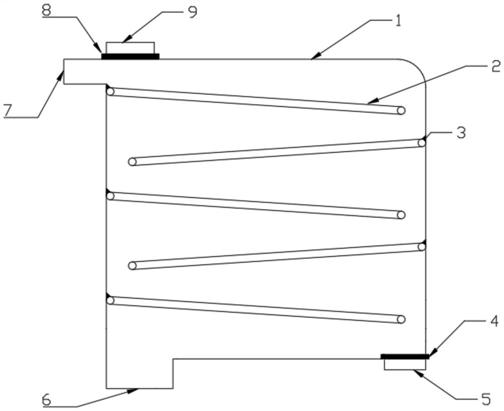
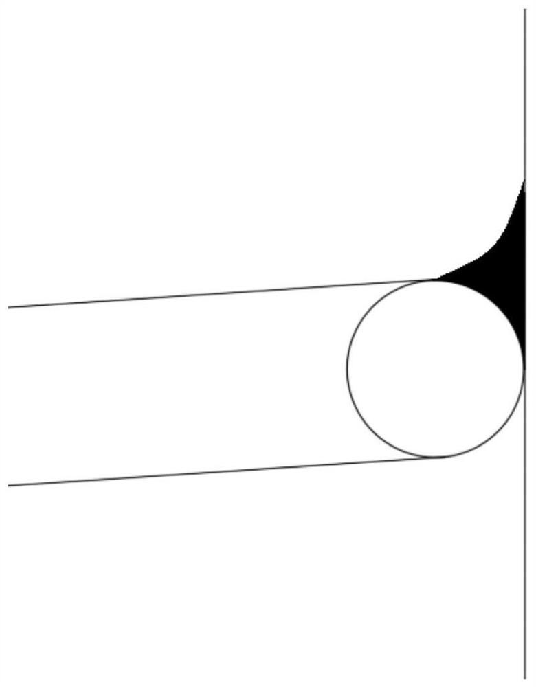
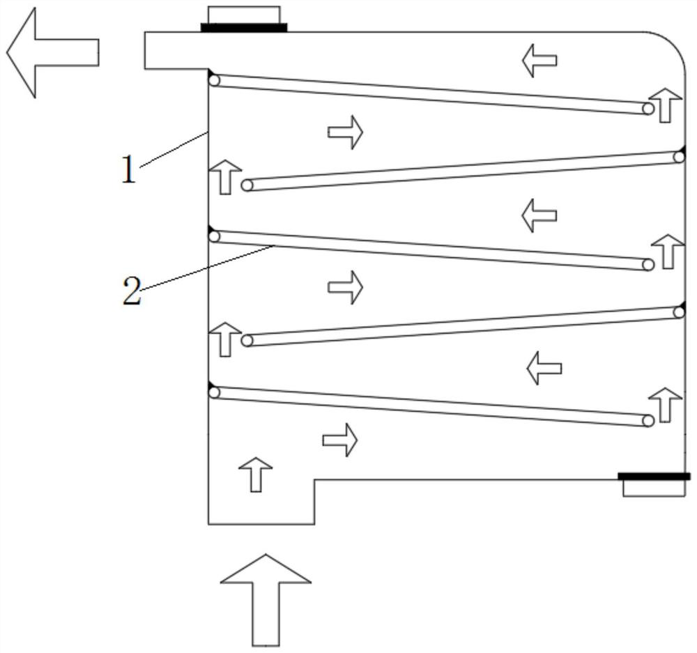
[0039] Such as figure 1 , is the staggered downward-inclining sludge drying device of the present invention. Several stages of staggered downward-inclining conveying mesh belts 2 are arranged in the drying box 1, and a large number of air holes are evenly distributed on the conveying mesh belt 2 surfaces. The drying box body 1 The upper part is provided with an air outlet 7 and a sludge inlet 9, and the bottom of the drying box 1 is provided with a sludge outlet 5 and an air inlet 6; And connect the return air treatment mechanism; the sludge feed port 9 is set above the beginning end of the uppermost conveying mesh belt 2; The discharge port 5 is located below the end of the lowest conveying mesh belt 2; the sludge discharge port 5 is provided with a discharge port valve 4, and the slud...


PUM


Abstract

The invention discloses a staggered declination type sludge drying device, and belongs to the technical field of sludge treatment. A plurality of stages of conveying mesh belts inclining downwards ina staggered mode are arranged in the drying box body, an air outlet and a sludge feeding port are formed in the upper portion of the drying box body, and a sludge discharging port and an air inlet areformed in the bottom of the drying box body. The air outlet is formed in one side of the starting end of the uppermost-stage conveying mesh belt, and the sludge feeding opening is formed above the starting end of the uppermost-stage conveying mesh belt; the air inlet is formed below the starting end of the lowermost-stage conveying mesh belt and connected with the hot air system, and the sludge outlet is formed below the tail end of the lowermost-stage conveying mesh belt; the sludge discharge port is provided with a discharge port valve, and the sludge feed port is provided with a feed portvalve; and a sealing strip is arranged in a gap between the starting end of each stage of conveying mesh belt and the side wall of the drying box body. The drying device is reasonable in structure andair path design, small in occupied space, high in drying efficiency and low in energy consumption.

Description

technical field [0001] The invention belongs to the technical field of sludge treatment, and in particular relates to a staggered down-tilt sludge drying device. Background technique [0002] In general, a sewage treatment plant can produce 5-8 tons of sludge with a moisture content of 80% for 10,000 tons of domestic sewage, and 10-30 tons of sludge for 10,000 tons of industrial sewage. Contrary to the continuous increasing trend of sludge production, the rate of sludge harmless treatment is still low. Landfill is still the main method of sludge treatment, and a large number of sewage plants are even dumped directly. In addition, urban sewage treatment enterprises have insufficient disposal capacity and outdated methods, and a large amount of sludge has not been treated in a standardized manner, directly causing "secondary pollution" and posing a serious threat to the ecological environment. [0003] The sludge produced by urban sewage treatment plants is difficult to be u...

Claims


Application Information

Patent Timeline
Patent Type & Authority Applications(China)
IPC IPC(8): C02F11/13
CPCC02F11/13
Inventor 李国嘉王晓坡朱璐璐
Owner XI AN JIAOTONG UNIV
Why Eureka
Eureka Blog
Learn More