
Feeding device applied to brake pad production

A feeding device and brake pad technology, applied in applications, household components, household appliances, etc., can solve the problems of unreasonable arrangement of the mainframe, poor flexibility, etc., and achieve good flattening effect, good preloading effect, and speed up production takt Effect

Active Publication Date: 2021-02-19
济南悦创液压机械制造有限公司
View PDF7 Cites 0 Cited by
  • Summary
  • Abstract
  • Description
  • Claims
  • Application Information

AI Technical Summary

Problems solved by technology

[0003] In order to improve the production efficiency of brake pads and reduce the cost of employment, there are already automatic production equipment for brake pad production. Driven by traditional driving methods, it can only do two-dimensional movement in the horizontal plane to load each hot press. Therefore, the hot presses in the existing automatic production equipment for brake pads can only be arranged in a straight line. , the flexibility is not good, and the host cannot be reasonably arranged according to the needs
[0004] The robot arm has good flexibility, but currently there is no feeding device that matches the robot arm

Method used


Image

  • Feeding device applied to brake pad production
  • Feeding device applied to brake pad production
  • Feeding device applied to brake pad production

Examples


Embodiment 2

[0106] The lower side of the transverse connecting plate 13 is provided with a raised portion corresponding to the pumping plate 12 one by one, and the lower side of the raised portion is located below the flat plate 11, behind the pumping plate 12 The upper side of the end part coincides with the lower side of the raised part, and is fixedly connected by welding to form a whole. All the other structures are the same as implementing Li Yi.

Embodiment 3

[0108] Two said rotating shafts 381 are respectively fixedly provided with driven gears between said first mounting plate 31 and said third mounting plate 33, and said two said driven gears are respectively fixedly arranged on said driving The driving gear on the power output shaft of the motor 382 is meshed, and all the other structures are the same as in the first embodiment.

Embodiment 4

[0110] The upper nozzle 3921 is fixedly arranged on the rear side of the brush 3811 on the first installation plate 31, and the lower nozzle is fixedly arranged on the rear side of the brush 3811 on the third installation plate 33, and The upper nozzle 3921 and the lower nozzle are respectively connected to the box for storing the release agent through pipelines. A submersible pump for pumping the release agent is arranged in the box. All the other structures are the same as in Embodiment 1.


PUM


Abstract

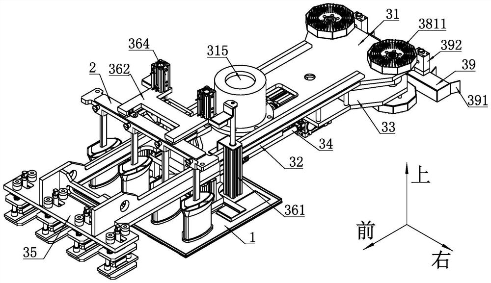
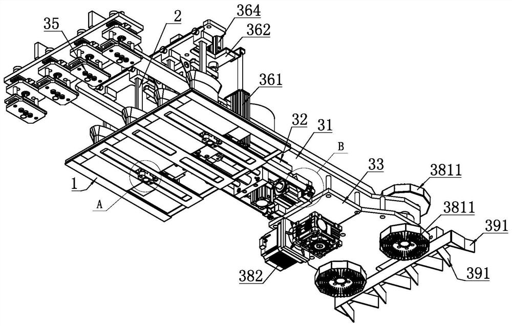
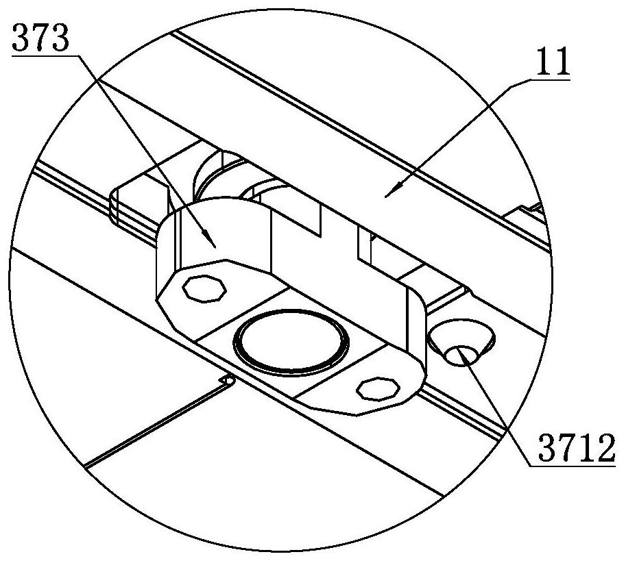
The invention discloses a feeding device applied to brake pad production, and relates to the technical field of brake pad machining equipment. The feeding device specifically comprises a first mounting plate, a second mounting plate slidably connected with the first mounting plate and a third mounting plate fixedly connected with the first mounting plate are sequentially arranged below the first mounting plate from front to back, and a material receiving air cylinder used for driving the second mounting plate to slide front and back is arranged between the second mounting plate and the first mounting plate. A steel backing picking component is arranged at the front end of the first mounting plate, and a second clamping assembly used for clamping a material box is arranged at the front endof the second mounting plate. The material box comprises a flat plate, a material guiding barrel and a drawing plate, a rodless air cylinder is arranged on the second mounting plate, a second positioning pin is arranged on an air cylinder sliding block of the rodless air cylinder, and when the second clamping assembly clamps the material box, the second positioning pin is inserted into a second positioning hole in the drawing plate. The feeding device can be matched with a robot arm and is good in flexibility.

Description

technical field [0001] The invention relates to the technical field of brake pad processing equipment, in particular to a feeding device used in brake production that can cooperate with a robot arm. Background technique [0002] With the development of the automobile industry, automobiles have become more and more widely used in people's lives, and the number of automobiles has increased year by year. The demand for brake pads, which are vulnerable parts of automobiles, continues to increase as the number of automobiles increases. [0003] In order to improve the production efficiency of brake pads and reduce the cost of employment, there are already automatic production equipment for brake pad production. Driven by traditional driving methods, it can only do two-dimensional movement in the horizontal plane to load each hot press. Therefore, the hot presses in the existing automatic production equipment for brake pads can only be arranged in a straight line. , the flexibil...

Claims


Application Information

Patent Timeline
IPC IPC(8): B29C43/34B29C43/18B29C37/00B29L31/16
CPCB29C43/34B29C43/18B29C37/0067B29C2043/3411B29C2043/3427B29L2031/16
Inventor 韩剑王超李磊
Owner 济南悦创液压机械制造有限公司
Learn More