
High-temporal-spatial-resolution multi-modal carrier dynamics measurement system and measurement method

A kinetic measurement, space-time resolution technology, applied in instrumentation, photovoltaic power generation, scanning probe technology, etc., can solve problems such as the inability to meet the requirements at the same time, the inability to achieve measurement, and the inability to provide information on the kinetics of electron-hole pair recombination luminescence. , to achieve great research value and application prospects, rich working modes, and flexible switching effects

Active Publication Date: 2021-02-19
付学文
View PDF8 Cites 7 Cited by
  • Summary
  • Abstract
  • Description
  • Claims
  • Application Information

AI Technical Summary

Problems solved by technology

However, because it uses ultrafast scanning secondary electron imaging, which is sensitive to the charge state of the sample surface, it can only detect the dynamic processes of charge carriers such as electrons and holes, transport, non-radiative recombination, etc. Given the recombination luminescence dynamics information of electron-hole pairs, excitons, etc., it is also impossible to obtain the kinetic information of the sample's comprehensive excited state energy carriers
[0006] To sum up, the existing measurement methods for the excited state energy carrier dynamics of low-dimensional optoelectronic functional materials either cannot meet the requirements of spatial resolution and time resolution at the same time, or can only measure one type of energy. The dynamic process of carriers cannot realize the ultra-high supersonication of charge-type carriers (such as electrons, holes, etc.) and neutral carriers (such as excitons, etc.) in the excited state at the same time Fast Kinetic Processes for Measurements

Method used


Image

  • High-temporal-spatial-resolution multi-modal carrier dynamics measurement system and measurement method
  • High-temporal-spatial-resolution multi-modal carrier dynamics measurement system and measurement method
  • High-temporal-spatial-resolution multi-modal carrier dynamics measurement system and measurement method

Examples


Embodiment Construction

[0035] Exemplary embodiments of the present invention will be described in more detail below with reference to the accompanying drawings. Although exemplary embodiments of the present invention are shown in the drawings, it should be understood that the invention may be embodied in various forms and should not be limited to the embodiments set forth herein. Rather, these embodiments are provided for more thorough understanding of the present invention and to fully convey the scope of the present invention to those skilled in the art.

[0036] It should be understood that the terminology used herein is for the purpose of describing particular example embodiments only and is not intended to be limiting. As used herein, the singular forms "a", "an" and "the" may also be meant to include the plural forms unless the context clearly dictates otherwise. The terms "comprising", "comprising", "containing" and "having" are inclusive and thus indicate the presence of stated features, st...


PUM


Abstract

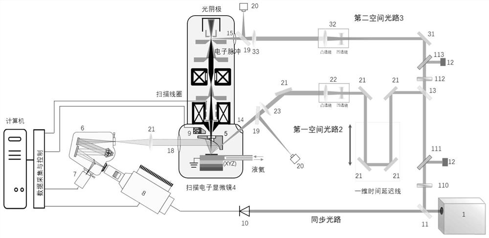
The invention relates to a high-temporal-spatial-resolution multi-modal carrier dynamics measurement system and measurement method. The measurement system comprises the steps that a femtosecond laserwhich emits near-infrared femtosecond laser; a wavelength selection light path which selects the wavelength of the near-infrared femtosecond laser; a first spatial light path which is used for exciting the surface of the sample to start an ultrafast carrier dynamic process; a second spatial light path which is used for carrying out ultrafast scanning imaging or excitation on the sample to generatetransient cathode fluorescence; a cathode fluorescence collector which is used for collecting transient cathode fluorescence excited on the surface of the sample; a spectrophotometer which is used for splitting the transient cathode fluorescence collected by the cathode fluorescence collector; an optical CCD which is used for carrying out spectral measurement of time integration on the transientcathode fluorescence split by the light splitting spectrometer; a time-resolved fluorescence detector which is used for measuring the transient cathode fluorescence spectrum split by the light splitting spectrometer; and a scanning electron microscope and scanning electron image detection system which is used for detecting a time-resolved scanning secondary electron image.

Description

technical field [0001] The invention relates to a high time-space resolution multi-mode carrier dynamics measurement system and measurement method, and relates to performance characterization of energy carrier dynamics of optoelectronic functional materials (such as nano-semiconductor materials, etc.) and new high-performance optoelectronic devices Develop technical fields. Background technique [0002] At present, various new low-dimensional optoelectronic functional materials, especially nano-semiconductor materials, are in the ascendant, and corresponding optoelectronic devices have also been widely developed. For most low-dimensional optoelectronic functional materials, the performance of their optoelectronic devices during service mainly depends on the dynamics of their excited state energy carriers, such as the transport, capture, energy Relaxation, recombination luminescence, etc., and most of these dynamic processes occur on the nanosecond to picosecond or even femt...

Claims


Application Information

Patent Timeline
Patent Type & Authority Applications(China)
IPC IPC(8): G01Q30/02
CPCG01Q30/02Y02E10/549
Inventor 付学文
Owner 付学文
Learn More