Waste gas combustion device with soot treatment function

A waste gas combustion and functional technology, applied in the direction of combustion method, combustion type, combustion equipment, etc., can solve the problems of large water consumption, air secondary pollution, waste of water resources, etc., to save water resources, good combustion effect, The effect of avoiding secondary pollution

A waste gas combustion and functional technology, applied in the direction of combustion method, combustion type, combustion equipment, etc., can solve the problems of large water consumption, air secondary pollution, waste of water resources, etc., to save water resources, good combustion effect, The effect of avoiding secondary pollution

CN112413612AInactive Publication Date: 2021-02-26南京伊都锦环保科技有限公司

Image

  • Waste gas combustion device with soot treatment function
  • Waste gas combustion device with soot treatment function
  • Waste gas combustion device with soot treatment function

Examples


Embodiment Construction

[0024] The present invention is described in further detail now in conjunction with accompanying drawing. These drawings are all simplified schematic diagrams, and only illustrate the basic structure of the present invention in a schematic manner, so they only show the configurations related to the present invention.

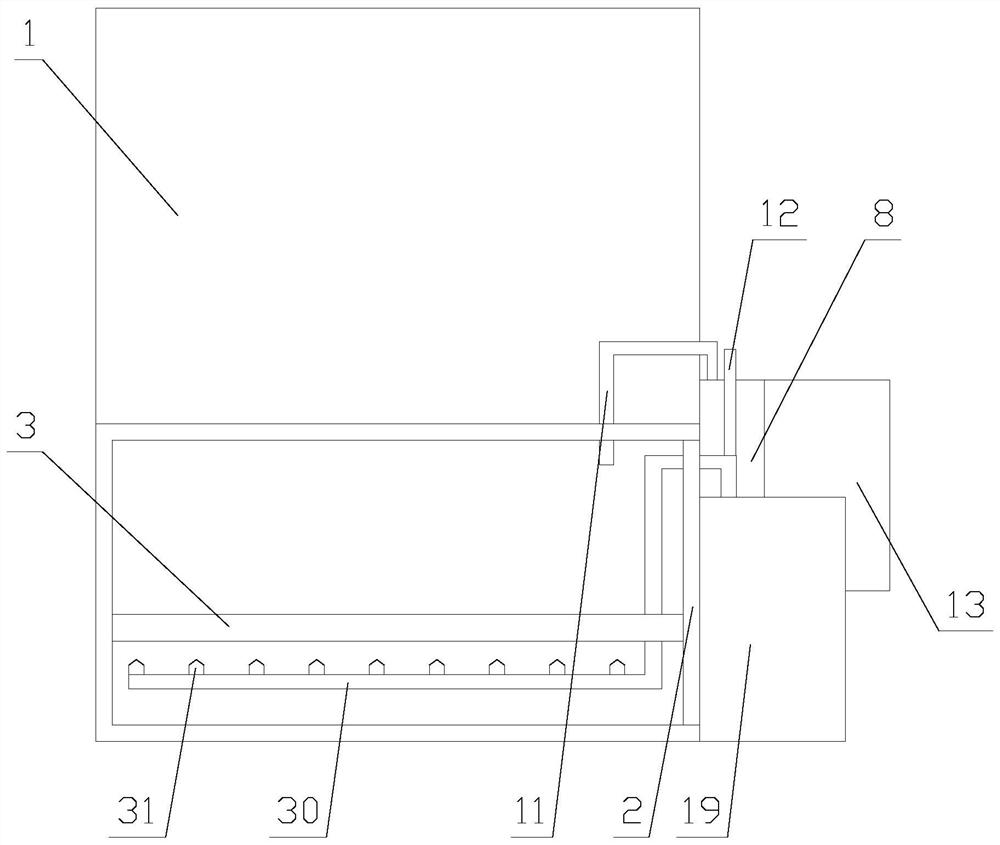
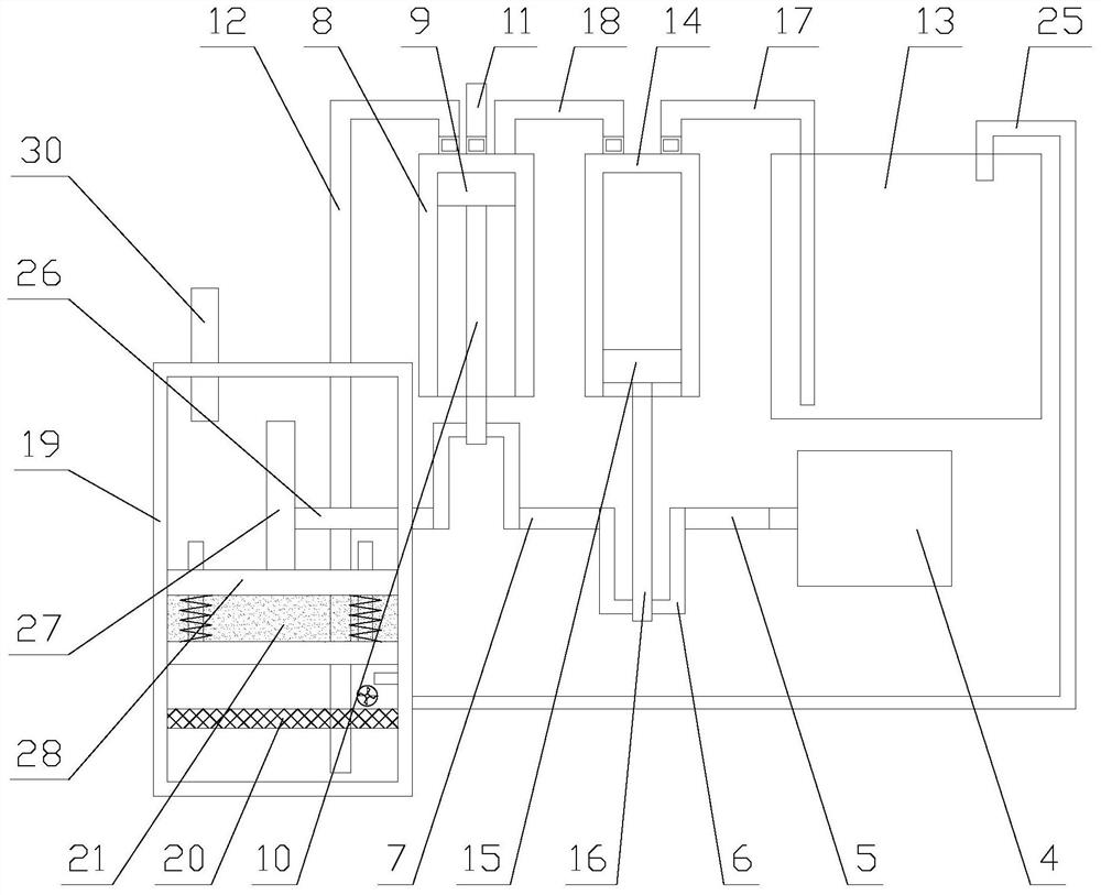
[0025] Such as figure 1 As shown, an exhaust gas combustion device with soot treatment function includes a main body 1, a cover plate 2, a bottom plate 3, a dust removal mechanism and a drying mechanism, the main body 1 is provided with an opening, and the cover plate 2 is arranged at the opening , the cover plate 2 is sealed and connected to the opening, the main body 1 is provided with a combustion chamber, the combustion chamber is arranged at the opening, the bottom plate 3 is arranged in the combustion chamber, and the dust removal mechanism and the air blowing mechanism are both arranged in the On the cover plate 2;

[0026] When the device is in use, op...


PUM


Abstract

The invention relates to a waste gas combustion device with a soot treatment function. The waste gas combustion device comprises a main body, a cover plate, a bottom plate, a dust removal mechanism and a drying mechanism, wherein the dust removal mechanism and an air blowing mechanism are both arranged on the cover plate. The waste gas combustion device with the soot treatment function achieves combustion treatment of waste gas by combusting coal and combusting the waste gas in the main body. Absorption treatment of soot is achieved through the dust removal mechanism, purified air is dried andblown through the drying mechanism, a better combustion effect is achieved, and meanwhile, filtering and cyclic utilization of water are achieved. Compared with an existing waste gas combustion treatment device, secondary pollution generated by soot is avoided through treatment of soot. Compared with an existing soot treatment device, a rotating shaft achieves online purification and dry air blowing of soot through linkage of the dust removal mechanism and the drying mechanism, so that a better combustion effect is achieved. Compared with an existing water purification mode, the device achieves cyclic utilization of water and saves water resources.

Description

technical field [0001] The invention relates to a waste gas combustion device with soot treatment function. Background technique [0002] The waste gas combustion device is a device for catalytic combustion of waste gas. The organic waste gas is preheated to 200-400°C through a heat exchanger first, and then enters the combustion chamber. When passing through the catalyst bed, the molecules of hydrocarbons and the oxygen molecules in the mixed gas are separated It is activated by being adsorbed on the surface of the catalyst. Because the surface adsorption reduces the activation energy of the reaction, hydrocarbons and oxygen molecules are rapidly oxidized at a lower temperature to produce carbon dioxide and water, thereby achieving the purpose of treating exhaust gas. [0003] Existing waste gas combustion devices are generally heated by burning coal, and when coal is burned, soot will also be produced, and soot will also cause secondary pollution to the air, while existing...

Claims


Application Information

Patent Timeline
26 Feb 2021
Publication
CN112413612A
IPC
F23G7/07; F23J15/00; F23L1/00; B01D29/01; B01D53/26
CPC
B01D29/01; B01D53/263; F23G7/07; F23J15/006; F23L1/00; Y02A50/20
Inventors
祝利东