Vacuum control system for atomic layer deposition coating machine

A technology of atomic layer deposition and vacuum control, which is applied in the direction of coating, gaseous chemical plating, metal material coating process, etc., can solve the problem of low vacuum degree of reaction, so as to improve film performance, vacuum degree and use efficiency and the effect of service life

Active Publication Date: 2021-03-02
INST OF OPTICS & ELECTRONICS - CHINESE ACAD OF SCI
View PDF6 Cites 0 Cited by
  • Summary
  • Abstract
  • Description
  • Claims
  • Application Information

AI Technical Summary

Problems solved by technology

[0004] The purpose of the present invention is to improve the deficiencies of low reaction vacuum degree in the existing atomic layer deposition coating technology, and provide a vacuum control system of atomic layer deposition coating machine, through With the cooperation of heat trap, control components and backing vacuum pump, the molecular pump is only used to obtain the background vacuum, which improves the efficiency and service life of the molecular pump and obtains a high background vacuum degree at the same time

Method used


Image

  • Vacuum control system for atomic layer deposition coating machine
  • Vacuum control system for atomic layer deposition coating machine
  • Vacuum control system for atomic layer deposition coating machine

Examples


Embodiment 1

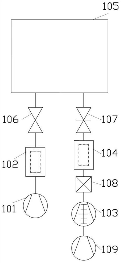
[0072] The present invention is realized by the following technical solutions, such as Figure 1-Figure 4 shown,

[0073] A vacuum control system of an atomic layer deposition coating machine, comprising an A fore-stage vacuum pump 101, a heat trap 102, a coating vacuum chamber 105, a control component 107, a heat trap 104, a control component 108, a molecular pump 103 ; the other end of the molecular pump 103 is connected to the B backstage vacuum pump 109 ; an A valve 106 is arranged between the A heat trap 102 and the coating vacuum chamber 105 .

[0074] During use, the reaction gas, the purge gas, and the metal precursor gas will respectively enter the coating vacuum chamber 105 and be adsorbed to the surface of the coating substrate. The metal precursor contains metal elements, which will cause damage to the molecular pump if it is adsorbed to the rotating bearing of the molecular pump. In order to prevent the metal precursor gas molecules from entering the molecular p...

Embodiment 2

[0077] In this embodiment, the structure of the B control component 108 is further refined on the basis of the above-mentioned first column.

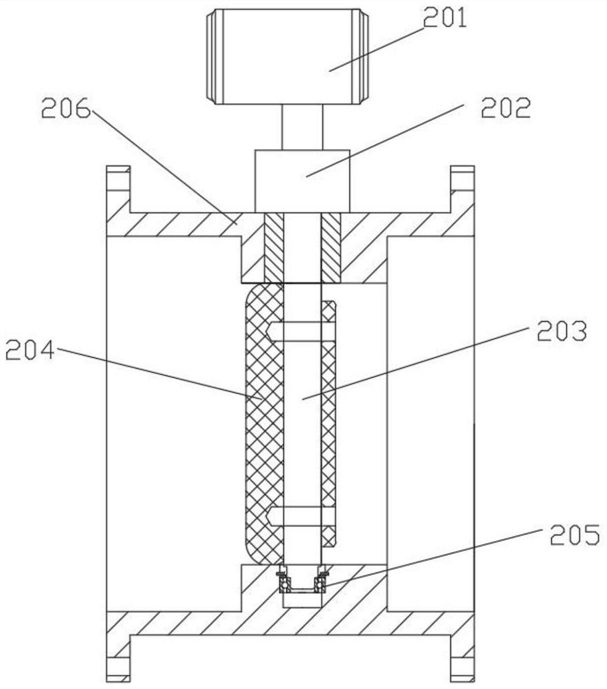
[0078] like figure 2 As shown, the B control assembly 108 includes a drive mechanism 201 disposed outside the pipeline, and an adjustment mechanism connected to the output end of the drive mechanism 201 and disposed in the pipeline.

[0079] The driving mechanism 201 is a rotating mechanism driven by a servo motor or a stepping motor.

[0080] Preferably, the adjustment mechanism includes a magnetic fluid sealing element 202 connected to the output end of the driving mechanism 201 and vacuum connected to the inner wall of the vacuum pipe 206, a rotating shaft 203 disposed in the vacuum pipe and connected to the output end of the magnetic fluid sealing element 202, a mounting A rotary bearing 205 on the inner wall of the vacuum pipe and rotatably connected with the rotary shaft 203 , and a valve plate 204 sleeved on the rotary shaft 20...

Embodiment 3

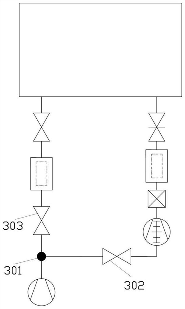
[0084] This embodiment is further optimized on the basis of the above-mentioned embodiment 1 or 2. The specific difference is that only one fore-stage vacuum pump is used in this embodiment, for example, only the A fore-stage vacuum pump 101 is used, and then a tee pipe 301 is used to make A fore-stage vacuum pump 101 is connected to the outlet of A heat trap 102 and the molecular pump 103 at the same time, a D valve 302 is arranged between the A fore-stage vacuum pump 101 and the outlet of the molecular pump 103; a D valve 302 is arranged between the A fore-stage vacuum pump 101 and the outlet of A heat trap 102 There is E valve 303.

[0085]Since the A fore-stage vacuum pump 101 is used to connect the outlet of the molecular pump 103 and the coating vacuum chamber 105 respectively, when using the molecular pump 103 and the A fore-stage vacuum pump 101 to cooperate to achieve vacuum, the connection between the A fore-stage vacuum pump 101 and the A heat trap 102 is The E valv...


PUM


Abstract

The invention discloses a vacuum control system for an atomic layer deposition coating machine, and relates to the technical field of vacuum coating. The vacuum control system comprises a hot trap A,a coating vacuum chamber, a control assembly A, a hot trap B, a control assembly B and a molecular pump which are sequentially connected through a pipeline, wherein the hot trap A and the molecular pump are both connected with fore vacuum pumps; and a valve A is arranged between the hot trap A and the coating vacuum chamber. According to the vacuum control system and the corresponding control method, on one hand, the base pressure and the coating vacuum degree of the atomic layer deposition coating machine can be effectively improved, so that the influence of residual physically adsorbed gas molecules on the properties of an atomic layer deposition film is reduced; and on the other hand, through cooperation of the hot trap B, the control assembly A and the fore vacuum pumps, the molecularpump is only used for obtaining the base pressure, so that the service efficiency of the molecular pump is improved and the service life of the molecular pump is prolonged.

Description

technical field [0001] The invention relates to the technical field of vacuum coating, in particular to a vacuum control system and a control method of an atomic layer deposition coating machine. Background technique [0002] Atomic layer deposition coating is a necessary technology for the processing technology of conductor chips and the surface coating of nanomaterials. The coating principle is as follows: two gas molecules that alternately enter the coating vacuum chamber are chemically adsorbed on the solid surface in turn, and a chemical reaction occurs on the surface to generate the desired film. The specific coating process is as follows: first, a reactive gas molecule enters the coating vacuum chamber and chemically adsorbs on the surface of the substrate as a single layer; then another gas enters the coating vacuum chamber and chemically reacts with the adsorbed molecules of the previous chemical adsorption. Restricted by the chemical bonds on the surface of the su...

Claims


Application Information

Patent Timeline
IPC IPC(8): C23C16/455C23C16/52
CPCC23C16/52C23C16/45525
Inventor 柳存定黎明杨伟
Owner INST OF OPTICS & ELECTRONICS - CHINESE ACAD OF SCI
Why Eureka
Try Eureka