
Fresh air ventilation system with heat recovery function

A technology for fresh air ventilation and heat recovery, which is applied in heat recovery systems, ventilation systems, and energy recovery systems for ventilation and heating. , to reduce maintenance costs, improve service life, and ensure the effect of purity

Inactive Publication Date: 2021-03-02
SUZHOU HUILIN ENERGY SAVING MATERIALS CO LTD
View PDF11 Cites 0 Cited by
  • Summary
  • Abstract
  • Description
  • Claims
  • Application Information

AI Technical Summary

Problems solved by technology

Therefore, the size of the fresh air volume has a great influence on the energy consumption of the building. It is necessary to consider both the indoor air quality and the energy consumption. Therefore, using a fresh air ventilator with heat recovery function to ensure the fresh air volume is currently a commonly used method, but the efficiency is generally high. Not high, there is still a part of exhaust heat that has not been recovered

Method used


Image

  • Fresh air ventilation system with heat recovery function

Examples


Embodiment Construction

[0024] The present invention will be described in detail below in conjunction with specific embodiments. The following examples will help those skilled in the art to further understand the present invention, but do not limit the present invention in any form. It should be noted that those skilled in the art can make several modifications and improvements without departing from the concept of the present invention. These all belong to the protection scope of the present invention.

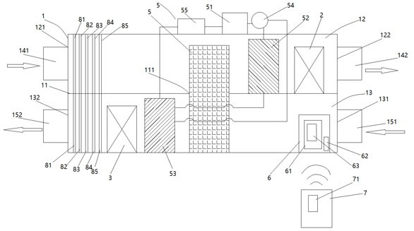
[0025] refer to figure 1 A fresh air ventilation system with heat recovery function according to the present invention, comprising: a cabinet 1 placed horizontally, a partition 11 is connected inside the cabinet 1, the partition 11 is arranged horizontally, and the partition 11 Divide the inner space of the chassis 1 into a fresh air compartment 12 and an exhaust compartment 13 arranged side by side from top to bottom. The opposite side walls of the chassis 1 corresponding to the fresh air compart...


PUM


Abstract

The invention provides a fresh air ventilation system with a heat recovery function. The fresh air ventilation system comprises a machine box, a fresh air fan, an exhaust air fan, a heat recovery heatexchanger, a heat pump heat exchanger set, an electric control box and a remote controller, wherein a partition plate is connected into the machine box, a fresh air inlet and a fresh air outlet are formed in two side walls corresponding to a fresh air partition chamber, and an exhaust air inlet and an exhaust air outlet are formed in two side walls corresponding to an exhaust air partition chamber; the fresh air inlet and the fresh air outlet correspondingly form a fresh air channel; the exhaust air inlet and the exhaust air outlet correspondingly form an exhaust air channel; the fresh air fan is erected at the inner side of the fresh air partition chamber; the exhaust air fan is erected at the inner side of the exhaust air partition chamber; the upper portion of the heat recovery heat exchanger is located in the fresh air partition chamber, and the lower portion of the heat recovery heat exchanger is located in the exhaust air partition chamber; and the heat pump heat exchanger set comprises a compressor, and an outlet is sequentially connected with a fresh air heat pump heat exchanger and an exhaust air heat pump heat exchanger through pipelines. According to the fresh air ventilation system, the heat recovery efficiency can reach 80% or above from 50% to the maximum; and meanwhile, through heat recovery of heat pumps, 100% recovery of air conditioner energy in exhaust air can be realized, additional cold and heat capacity can be generated, and the requirement of a user for the fresh air temperature is met.

Description

technical field [0001] The invention belongs to the technical field of fresh air ventilation, and in particular relates to a fresh air ventilation system with heat recovery function. Background technique [0002] With the improvement of people's material life, the requirements for indoor air quality have also increased significantly. Therefore, regular and quantitative organized ventilation has been paid more and more attention by people, and it has also become an important indicator for evaluating the grade of indoor environment. Therefore, the market for fresh air ventilators will become larger and larger, and it will surely become one of the must-installed equipment for indoor air treatment. [0003] With the improvement of the airtightness of the enclosure structure and the adoption of measures such as minimizing the intrusion of outdoor cold wind in order to achieve the effect of heat preservation, the discharge or dilution of indoor pollutants is not timely. People in ...

Claims


Application Information

Patent Timeline
IPC IPC(8): F24F5/00F24F7/08F24F7/003F24F3/16F24F11/56F24F11/84F24F11/88F24F11/89F24F12/00F24F13/20F24F13/28F24F13/30F24F8/108F24F8/15F24F8/158F24F8/24
CPCF24F5/001F24F7/08F24F12/002F24F13/20F24F13/28F24F13/30F24F2012/005F24F2013/202F24F2013/205F24F11/56F24F11/84F24F11/88F24F11/89Y02B30/52Y02B30/56
Inventor 陈磊仲华
Owner SUZHOU HUILIN ENERGY SAVING MATERIALS CO LTD
Learn More