Efficient asphalt melting device for road construction

A technology of road construction and melting device, which is applied in the direction of roads, roads, road repairs, etc., can solve the problems of reduced melting rate and large area of ​​solid asphalt, and achieve the effects of ensuring stability, avoiding waste, and accelerating melting efficiency

Inactive Publication Date: 2021-03-09
李好宣
View PDF1 Cites 3 Cited by
  • Summary
  • Abstract
  • Description
  • Claims
  • Application Information

AI Technical Summary

Problems solved by technology

A high-efficiency asphalt melting device for road construction in the above-mentioned patent has

Method used


Image

  • Efficient asphalt melting device for road construction
  • Efficient asphalt melting device for road construction
  • Efficient asphalt melting device for road construction

Examples


Embodiment 1

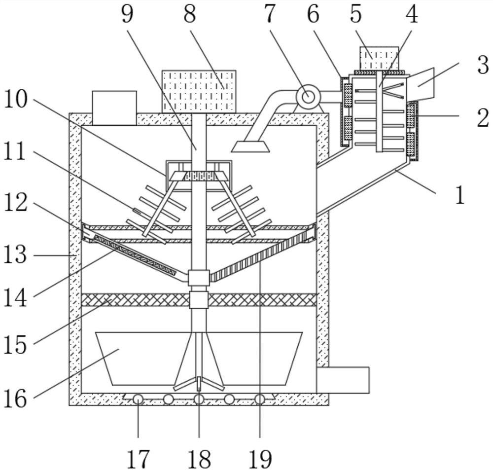
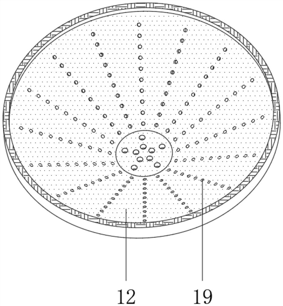
[0026] refer to Figure 1-4 , an asphalt high-efficiency melting device for road construction, comprising a housing 13, a crushing cylinder 1 is fixedly inserted into the upper end of the outer wall of one side of the housing 13, and a crushing motor 5 is installed on the top of the crushing cylinder 1 through bolts, and the bottom end of the crushing motor 5 passes through The coupling rotates and installs a crushing roller 4, and the upper end of the peripheral outer wall of the crushing roller 4 is fixedly equipped with a scraping rod, and the middle and lower end of the peripheral outer wall of the crushing roller 4 is fixedly installed with crushing rods that are equally spaced and successively reduced. There is a feed hopper 3, and the outer wall of the crushing cylinder 1 is plugged with equidistant semiconductor refrigeration chips 2, the outer wall of the crushing cylinder 1 is fixedly installed with a heat recovery sleeve 6, and the outer wall of the top end of the sh...

Embodiment 2

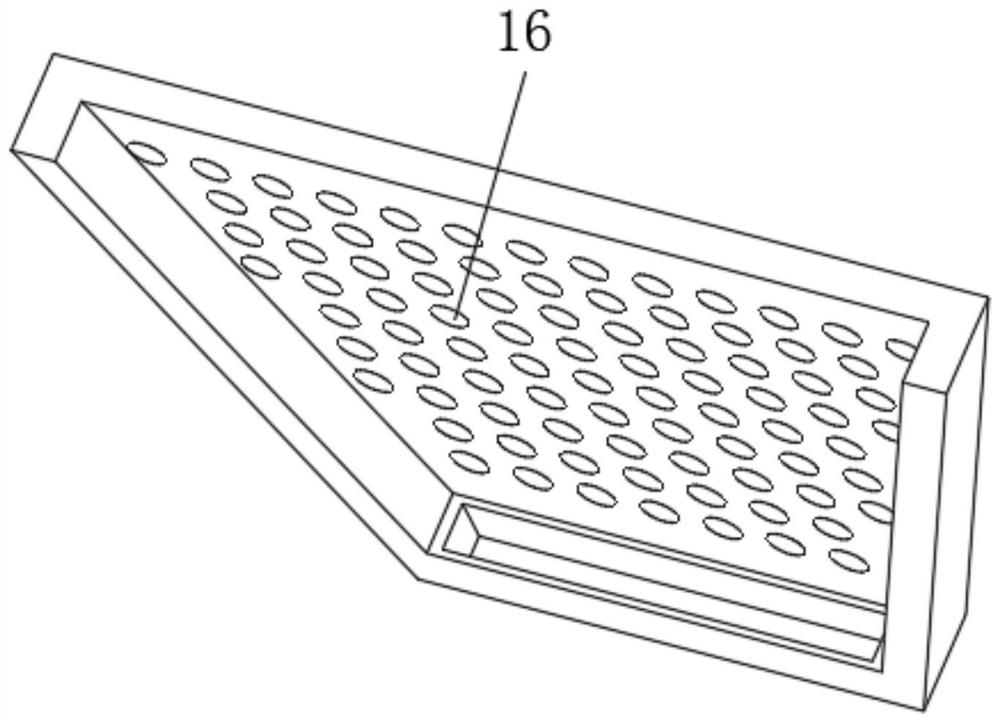
[0036] refer to Figure 5 , a high-efficiency asphalt melting device for road construction, further, a feeding cylinder 21 is inserted on one side of the housing 13, and a sealing ring is inlaid at the connection between the feeding cylinder 21 and the housing 13, and the feeding cylinder 21 is located on the ring slide rail At the lower end, the outer wall of one side of the feeding cylinder 21 is provided with a feeding motor 20 through bolts, and the feeding motor 20 is fixedly installed with a screw feeding blade 22 through a rotating shaft, and the outer wall of the other side of the feeding cylinder 21 is provided with a drug outlet, and the top of the feeding cylinder 21 is fixed at an angle. A medicine feeding hopper is plugged in, and a support frame is installed between the lower end of the outer wall on one side of the housing 13 and the feeding cylinder 21 through bolts.

[0037] Working principle: The feeding cylinder 21 is inserted through one side of the housing...


PUM


Abstract

The invention belongs to the technical field of road construction, and particularly relates to an efficient asphalt melting device for road construction. Aiming at the problem that the melting rate isreduced due to the fact that the area of existing solid asphalt is larger, the efficient asphalt melting device comprises a shell, a crushing cylinder is fixedly inserted into the upper end of the outer wall of one side of the shell, a crushing motor is installed at the top end of the crushing cylinder through bolts, a crushing roller is rotatably installed at the bottom end of the crushing motorthrough a shaft coupling, and a scraping rod is fixedly installed at the upper end of the circumferential outer wall of the crushing roller. The crushing motor, the crushing roller, the scraping rodand the crushing rod are arranged in the crushing cylinder to crush large-size solid asphalt, semiconductor chilling plates are inserted into the outer wall of the crushing cylinder at equal intervals, crushing of the solid asphalt is accelerated in an assisted mode according to low-temperature brittleness and hardness of the asphalt, a first stirring frame, a crushing hopper, a second stirring frame, a third stirring frame and an electric heating filter screen are arranged on the outer wall of the circumference of the stirring shaft, solid-liquid mixed asphalt is centrifugally separated, heated and mixed, and the melting efficiency of the asphalt is greatly improved.

Description

technical field [0001] The invention relates to the technical field of road construction, in particular to an asphalt high-efficiency melting device for road construction. Background technique [0002] Highway engineering refers to the survey, measurement, design, construction, maintenance, management, etc. of highway structures. Highway engineering structures include roadbeds, pavements, bridges, culverts, tunnels, drainage systems, safety protection facilities, greening and traffic monitoring facilities. As well as houses, workshops and other service facilities used for construction, maintenance and monitoring; among them, road construction includes asphalt paving, which is a dark brown complex mixture composed of different molecular weight hydrocarbons and their non-metallic derivatives. Waterproof, moisture-proof and anti-corrosion organic gelling material; asphalt can be mainly divided into three types: coal tar pitch, petroleum pitch and natural pitch: coal tar pitch i...

Claims


Application Information

Patent Timeline
IPC IPC(8): E01C19/10E01C19/05
CPCE01C19/05E01C19/10E01C19/104E01C19/1068
Inventor 李好宣
Owner 李好宣
Why Eureka
Try Eureka