
Biomass combustion heating injection furnace

A biomass and furnace technology, applied in steam boilers, steam generation, steam generation devices, etc., can solve the problems of low thermal internal energy conversion efficiency, low flue gas emissions, energy waste, etc., to facilitate unified treatment, prevent material Waste, the effect of improving combustion efficiency

Inactive Publication Date: 2021-03-09
绍兴中松智能科技有限公司
View PDF0 Cites 0 Cited by
  • Summary
  • Abstract
  • Description
  • Claims
  • Application Information

AI Technical Summary

Problems solved by technology

[0002] Biomass pellet fuel is mostly a block fuel produced by processing stem crops, peanut shells, bark, sawdust and solid waste (furfural slag, edible fungus slag, etc.). It is a renewable energy source with low cost and can replace Coal is used as energy for life and production. Therefore, biomass fuel is favored by the majority of users. Biomass stoves are a kind of equipment that has developed rapidly in recent years. It has changed the heating method of traditional stoves that use coal as fuel. , using all combustible biomass such as straw and rice straw as fuel, there are both open flame combustion and gasification components in the furnace, with the advantages of no tar, no black smoke, sufficient combustion, high thermal efficiency, and low smoke emission, which is very suitable for rural areas Household use, however, when the existing biomass burning furnace is used, its thermal internal energy conversion efficiency is low, which easily leads to a large amount of heat loss and energy waste

Method used


Image

  • Biomass combustion heating injection furnace
  • Biomass combustion heating injection furnace
  • Biomass combustion heating injection furnace

Examples


Embodiment Construction

[0029]The following will clearly and completely describe the technical solutions in the embodiments of the present invention with reference to the accompanying drawings in the embodiments of the present invention. Obviously, the described embodiments are only some, not all, embodiments of the present invention. Based on the embodiments of the present invention, all other embodiments obtained by persons of ordinary skill in the art without making creative efforts belong to the protection scope of the present invention.

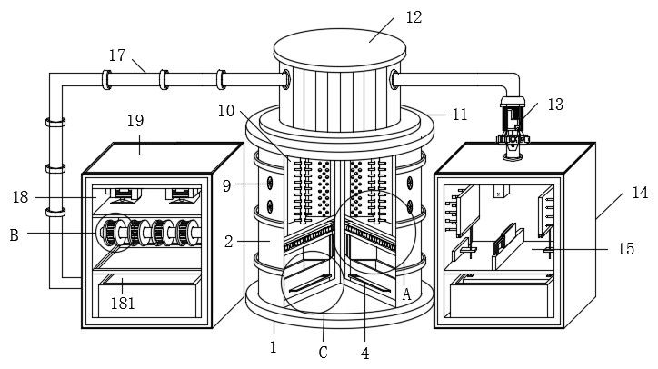
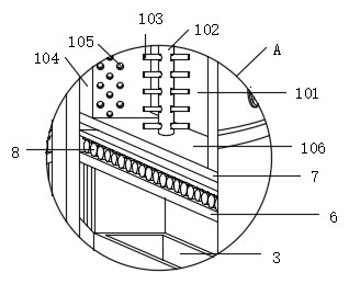
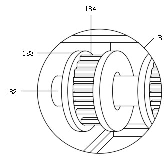
[0030] see Figure 1-7 , the present invention provides a technical solution: a biomass combustion heating injection furnace, including a furnace body shell 2, a combustion mechanism 10, a high-temperature steam chamber 12, a primary power generation box 14, a magnetic fluid power generation mechanism 15, and a secondary power generation box 19 and the steam generating mechanism 18, the furnace body base 1 is fixedly installed on the bottom end panel of the fur...


PUM


Abstract

The invention discloses a biomass combustion heating injection furnace. The furnace comprises a furnace body shell, a combustion mechanism, a high-temperature steam chamber, a first-stage power generation box, a magnetofluid power generation mechanism, a second-stage power generation box and a steam power generation mechanism, wherein a furnace body base is fixedly mounted on a panel at the bottomend of the furnace body shell through fixing bolts, a residue collection box is fixedly mounted in the bottom end of the furnace body shell through fixing bolts, residue drawer plates are movably connected to the outer wall of one side of the residue collection box, and a handle is fixedly mounted on the outer wall of each residue drawer plate. The biomass combustion heating injection furnace hasthe beneficial effects that in the using process, the combustion work of biomass can be completed, the combustion work is thorough, and resource waste and resource utilization rate reduction an be effectively prevented; meanwhile, after combustion is completed, steam power generation work and magnetofluid power generation work can be completed respectively, a good energy conversion effect is achieved, environmental pollution is little, a good clean power generation effect is achieved, and the environmental protection performance is improved; and the furnace is simple in structure, reasonablein layout and suitable for application and popularization.

Description

technical field [0001] The invention relates to the technical field of injection furnaces, in particular to a biomass combustion heating injection furnace. Background technique [0002] Biomass pellet fuel is mostly a block fuel produced by processing stem crops, peanut shells, bark, sawdust and solid waste (furfural slag, edible fungus slag, etc.). It is a renewable energy source with low cost and can replace Coal is used as energy for life and production. Therefore, biomass fuel is favored by the majority of users. Biomass stoves are a kind of equipment that has developed rapidly in recent years. It has changed the heating method of traditional stoves that use coal as fuel. , using all combustible biomass such as straw and rice straw as fuel, there are both open flame combustion and gasification components in the furnace, with the advantages of no tar, no black smoke, sufficient combustion, high thermal efficiency, and low smoke emission, which is very suitable for rural a...

Claims


Application Information

Patent Timeline
Patent Type & Authority Applications(China)
IPC IPC(8): F22B31/00F22B33/18F01K11/02F01D15/10H02K44/08H02K44/10
CPCF01D15/10F01K11/02F22B31/00F22B33/18H02K44/08H02K44/10
Inventor 林玉娟
Owner 绍兴中松智能科技有限公司
Learn More